• The move to the new server is done. There are some software and database maintenance updates in process. This has us passing the hat around to help out. We appreciate any donations. Seriously, even a dollar helps. The payment page may be found here - https://www.audiokarma.org/support.html

Working on a 2250B power supply, have a question

33713

Active Member
Hey All, I recently acquired a pristine 2250B. I have done a few recaps on others and have ahd some good luck, so I started this one with a kit from ebay. I already asked the seller about this, but I am still hesitant to dim bulb test it after the recap.

Part C808, 47uf/16V was provided in this kit as a green bipolar. The seller has told me this is in the signal path and is intentional.

Does this make sense?

Also, the other one provided as bipolar is the C807, 4.7/50V. I also just read that this could be replaced with a 10uf as per original manual.

Any info would be appreciated before I Dim Bulb it.

Thanks Everyone!
 
Register to hide this ad
What are your concerns about the dim bulb tester (DBT)? The DBT protects the amp from possible shorts, so you shouldn’t worry about using it.
I’m unsure of your concerns with the caps mentioned. Is it because they’re bipolar and the originals were polarized? That shouldn’t be an issue.
Also, going from 4.7uf to 10uf is not anything serious to worry yourself over, although I would rather remain at the original 4.7uf.
 
What are your concerns about the dim bulb tester (DBT)? The DBT protects the amp from possible shorts, so you shouldn’t worry about using it.
I’m unsure of your concerns with the caps mentioned. Is it because they’re bipolar and the originals were polarized? That shouldn’t be an issue.
Also, going from 4.7uf to 10uf is not anything serious to worry yourself over, although I would rather remain at the original 4.7uf.
Hey there, that was quick, TY. Yes, my concern is the change on the larger one. I was not expecting to go to a bipolar there. On other kits/amps I have in the past, but it's usually for the 1,2's and 3's on the tone/pre or amp boards.

Even using DBT, I fear disasters. I also can't picture how a cap in the PS is on the signal as the seller mentioned. I am good at R&R and learn a bit every time I go through one of these recaps/transistors.

so have at it?
 
Cap C808 is NOT in the audio path. Nothing is on this board! Folks will argue that caps in the filtering parts sound better if they're something upgraded, say audio type. Not here to start THAT up again! My position is that low ESR caps are the best choice for that. But C808 is not one of those.

Cap C807 is the filter for the relay supply, and is a small value to have the relay turn off quickly at power off to avoid audible popping. A 10uF would double the time for that which may or may not cause an issue. I'd use the 4.7 myself. This cap is not in the filtering side of things and the type is not critical.

No concerns with either being non-polar.
 
Even using DBT, I fear disasters. I also can't picture how a cap in the PS is on the signal as the seller mentioned. I am good at R&R and learn a bit every time I go through one of these recaps/transistors.
so have at it?
I would prefer to use the 4.7uf over the 10uf. But it won't be an issue using the DBT, so go for it and let us know your results.
 
OK, I am back thinking about this project. I looked everything over and so far everything looks good. I recapped the PS board, changed the 1318's to 2383's as per kit, and installed the new filter capacitors. I have yet to turn it on. Some more information about this receiver.

It's about as mint as one could be with a OEM walnut case, but I bought it knowing that it turned on, but does not produce sound. I have determined that the relay is good, but does not activate. So, I ordered a kit for it from ebay and decided to proceed with recapping the PS in hopes that I may find some open capacitor or something on the board, but did not. Some ESR, yes, but the values were all pretty good. So, I think if I am to DBT it, it will power on, but I do not think anything will change and it's likely still in some sort of protection. Could powering it on after these new caps cause me any new damage?

I do have a local repair guy that is very good with Marantz, which is why I proceeded down this path. But now I am second guessing the path.

I did test the output transistors in circuit and they seem to be ok. My goal is not to ask for repair help, but minimize any more damage, but if there are some easy tests that might help my situation, I am all for trying them, as I would be pretty happy to not bring it over to him. I also was thinking, should I do the tone and amp board and see if I find some bad caps or transistors that way?

Thanks!
 
Pulled one pair of output transistors this am and have a tester coming. Already I see that one is passing basic diode test on my DMM in both directions. They are marantz branded originals.

@eiraved

@rBuckner

 
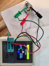
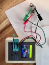
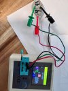
Well, I got my little transistor/diode tester in, and pulled the outputs. Is this a sign that they are all good still, but with 13%and 15% mismatch/variance that will affect crossover distortion? I would assume that I should get some new ones in there with this much of a variance? Maybe I just need to power it up and check for DC?

Note, I labeled them as they came off, 1,2,3,4 and the 53 and 54 is the end or the Marantz part number
 

Attachments

  • IMG_0371.jpg
    IMG_0371.jpg
    114 KB · Views: 17
  • IMG_0372.jpg
    IMG_0372.jpg
    105.1 KB · Views: 16
  • IMG_0373.jpg
    IMG_0373.jpg
    108.7 KB · Views: 16
  • IMG_0375.jpg
    IMG_0375.jpg
    111.5 KB · Views: 16
Maybe I just need to power it up and check for DC?
^^This^^. Install the good transistors then power while using the DBT to verify there are no shorts first.

Take a look at Echowars thread on DC offset to get a good understanding of what is considered good/bad regarding the offset (if you haven't already):
 
Last edited:
Nope, not related. A lack of bias makes for crossover distortion. I look for hfe to be >12 in outputs.
Thanks! So I was wondering, I am waiting for some new T0-3 Silicone pads, but they are gonna be a bit. I think i read somewhere that you could power this up without them in. I am curious if I can do that safely, and see what the DC offset is so I can keep thinking about where to go with this. Thanks!
 
Also, I changed the 3 1318 transistors on that board when I recapped it. I tested them in my new tester. 1 was bad. I am not sure which position that was in, but what are the odds I got lucky by replacing it and now the receiver is in better shape?
 
Thanks! So I was wondering, I am waiting for some new T0-3 Silicone pads, but they are gonna be a bit. I think i read somewhere that you could power this up without them in. I am curious if I can do that safely, and see what the DC offset is so I can keep thinking about where to go with this. Thanks!
You can, but he final bias needs to have the outputs in place. Just make sure the output transistor sockets are wrapped up in a piece of towel or a rag so they can't short to anything.
 
Well, I got the pads today and re installed the output transistors instead of being impatient.

The amp powers on, but there is no relay click still.

No DC at speaker outputs.

So, the receiver is back to where it was when I got it, except for the recapped/partially rebuilt power board

I am not sure where I can look on the power board forDC, can someone tell me? Thanks!
 
There will be no DC on the speaker outputs since the relay did not engage. You need to check the DC before it goes into the relay.
This is what I was wondering how could there be DC if that board is not energized. So, where would I measure that? I have a great schematic here that I am trying to wrap my head around, but it is over my head for the most part. I understand some, but not enough.

 
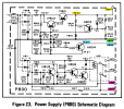
If you want to verify that the Power supply is producing DC voltages, look at the schematic for the P800 Power Supply.
  • Set your DVM to measure DC volts, black lead on J805 (or chassis ground), red lead on J804... it should read about 35VDC.
  • Now, check the other voltage. Black lead on J805, red lead on J806... it should read about 14VDC.
  • You can also check the DC coming from the Main Amp boards on J809 and J810. It should be in the millivolt range.
  • You need to have 24V across H812 (relay coil) in order for the relay to engage.
  • The circuitry of H805, H806, and H807 check for excess DC on the Main Amp outputs and doesn't allow the relay to activate to connect the speakers.
1788228759687.png
Here it is on the board layout.
1788228921012.png
 
Last edited:
OK, Thank You. I had been checking these out, and knew I had to adjust the PS voltage which I have done before 804-805=35V ( I set it)

This one I noticed is weird, the schematic calls for 14, but here is what I noticed earlier, 805-806 apx 14V when on any Tuner input, apx 12.3 when on Aux/Phono etc????

Lastly, 809-810 33.5V, not mv, V
 
Back
Top Bottom