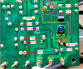
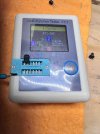
What were the other 5 diode test measurements for each?H707 Marked D438E-5J C>E OL
H710: Marked C945A0962 E>C OL
H714 Marked 069 D415 E>C OL
H715 Marked 068 B549 E>C OL


What were the other 5 diode test measurements for each?H707 Marked D438E-5J C>E OL
H710: Marked C945A0962 E>C OL
H714 Marked 069 D415 E>C OL
H715 Marked 068 B549 E>C OL
Sorry, started thinking that we were only focused on E>C. I will get each today.ThanksWhat were the other 5 diode test measurements for each?
Alright, again sorry for my confusion. I have every transistor out right now.would testing each of them with the transistor tester be as helpful? I can take each one, hook it up, and upload pictures of each one labeled by position. Thanks!The diode test might provide some information for testing without unsoldering the transistor from the board. I'm not sure if you need to remove it to use the transistor tester?
Just use diode test on DMM for these. Write down what you measure.
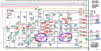
Red and black leads shown in color below.
- B-C
- C-B
- B-E
- E-B
- C-E
- E-C


OK, thanks for the synopsis and input. I think I will be digging into the other amp board tonight or tomorrow to see if the same parts are on it as we found here. I will not unsolder anything until we prove that that board works as designed.OK, based on your measurements on the transistor tester I made the following table.
View attachment 3831569
- One thing to note is that H711 (A733) tested as an NPN transistor, but the datasheet for the 2SA733 is for a PNP (and also shown on the schematic as a PNP).
- I don't know where that transistor came from, but it looks to be incorrect. (mislabeled or counterfeit part)
- H702/703 on the schematic is a 2SA763. You have installed a 2SA750 and the recommended new part is a KSA992FBU. (just make sure the leads are the same)
- H707 on the schematic is a 2SC875. You have a 2SD438 installed and the recommended new part is a KSC2383Y.
- At a minimum, I would replace H711 with a proper new set of replacements from Digikey or Mouser.
- Might as well replace H702/H703 and H707 at the same time.
- What transistor parts are in the other good channel, the same or original parts?
View attachment 3831595
View attachment 3831571View attachment 3831574

You know, I am due to place an order with Affinity anyway, so I will make sure to get the more robust ones. Also, just a note, I moved around the left amplifier enough to confirm that each part in it is identical to the right channel. So, in my estimation all of these parts came from Marantz in the original build. That makes me interested in testing that 733 to see whether it reads NPN or PNP. Maybe the right channel one is damaged and reading odd?Unless the caps are bulging or leaking, I would fix the issue first, get the board working, then go back and recap it. That way you are starting from a known good starting point so when you recap it and it doesn't work you know what you had changed.
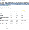
The biggest difference between the KSA992FBU and 2SA733 or KSA733 is the maximum collector current (see below). Only 50mA vs 100 to 150mA for the original 2SA733.
I don't know how much collector current is drawn by the circuit so it may work/or not.
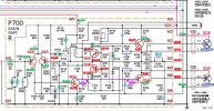
If you examine the schematic that I attached above, you will see that all of the "red" measured voltages occur after H711. My guess is that when you replace it with a real KSA733 that will all be good (unless it caused additional damage).
View attachment 3831681
You can get the KSA733 on e--y from a reputable seller and AK member (no affiliation with seller). Otherwise, they are discontinued on Digikey or Mouser.
View attachment 3831697
I bought it from the 80 year old original owner. Genuine nice guy with no reason to lie about it. I also took his altec bookshelves that he used with it. He knew it no longer produced sound, but powered on. He had a tech look at it quickly but was quoted and crazy amount to fix it and decided to part with it. To me, those boards look untouched, but who knows?Did this receiver ever work while you owned it, or did you buy it as a repair?
The Plot thickens the marked one, is from the board we have been evaluating.Did this receiver ever work while you owned it, or did you buy it as a repair?
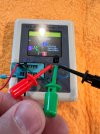
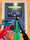
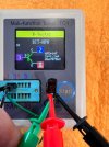
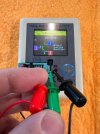
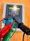
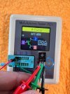
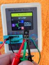
Whoops, I uploaded the wrong pictures. I updated them above. These are now pictures of the 733's, not the 750's which I mistakenly uploaded. The one marked fully on top is the one from the board we have been picking apart, the other one is from the board that has a good DC reading at the PS board. So these are measuring the same and are coming up NPN when they call for PNP.Probably should also replace those. I think they should be closely matched for that configuration.
What are you trying to show me above?
You keep confusing me. Your two updated photos in post #73 are the H711 from the two boards (one good channel, one bad channel).So these are measuring the same and are coming up NPN when they call for PNP.
I'm not sure what you are saying. It looks OK, you pulled the 2SA733, the schematic and PL show they should be 2SA733, it looks like they test good.In my mind, there is no way this did not work it's whole life with the 733's in there.
Ahh, sorry I confused myself. I didn't realize that the "first" 2SA733 actually read differently. What I picked up on was that they matched. So yes, upon retesting the 2SA733, it appears now that it was the correct type of part, is good, and same for the other channel. I briefly thought that we had the wrong part type in both channels.You keep confusing me. Your two updated photos in post #73 are the H711 from the two boards (one good channel, one bad channel).
They BOTH show as PNP on your tester.
The schematic shows that they should be PNP.
Your original photo showed them as NPN, but you say that you uploaded the wrong photo.
What did you mean by your statement above?
I'm not sure what you are saying. It looks OK, you pulled the 2SA733, the schematic and PL show they should be 2SA733, it looks like they test good.
What is your concern??
Hello, I can do that. Can I do it with the Right Channel amp restored to hopefully working condition (all I did was remove and reinstall the H711/733), and the outputs for access, I would still need to put those back in. The Left Channel has transistors removed, should I begin to put them back in? I do have some 2383's here, and also some 1845's. That leaves me to the decision of reusing the 733's or not, I believe.Can you please verify these two voltages (shown with purple arrows)?
Previous measurements showed one was 0.3v the other was 33.2v?
View attachment 3832183