• The move to the new server is done. There are some software and database maintenance updates in process. This has us passing the hat around to help out. We appreciate any donations. Seriously, even a dollar helps. The payment page may be found here - https://www.audiokarma.org/support.html

Yamaha C4 preamp fault. Hum. Phono switches.

Thanks Nashou.
My A-1, after servicing was finally running great but...
Was getting an occasional ‘static, crunching cardboard at volume’ sound through the left channel. Swapped the 2SK100’s and the problem disappeared on the left channel but occurred on the right channel!
Tested the likely faulty 2Sk100 on the transistor tester and one set of three pins gave a very different reading.
I will look again at those legs though, good point.
Any view on the JFE2140?
Apparently it’s very low noise, the internal FETS are very tightly matched, and thermally very tightly coordinated.

Is there a board to mount them to that would fit the current package the A-1 uses?

Athanasios

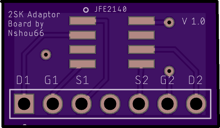
Well I decided too make a board or attempt to . It should fit in the A-1 Driver board and two back to
back will also fit. I need too add a coper plane to the back side still. May work we'll with out it just thinking of noise reduction with it.

The chip data is here JFE2140 The experts here would need to chime in if it will or if another dual Jfet
SOIC 8 chip would be better.

Here is the board layout 17mm wide by 11 mm high.

51980902423_d48b49e9a9_b.jpg


Athanasios
 
Well I made the adapter board for the JFE 2140 . Still need to test it in circuit. Might be next week or the week after.

Here are the pics and the test from my DCA pro75

52079353830_5d706560ab_h.jpg


These are the graphs of #1 board with each half of the 2140 , as you can see they match very well.

52079350780_ef0d94ff23_b.jpg


52078863306_1b9e1bc22b_b.jpg


And #2 Board

52079350770_52a1af37da_b.jpg


52079099429_8751edffb3_b.jpg


Athanasios
 
A beautiful set of images, very neat work!
So the individual elements are:
Custom pcb,
JFE2140,
and the pins (7 individual ones per board or are they already linked and one just breaks off a set of 7?)
Hope that it performs well once it’s in circuit.
Good luck!
 
Well its a no go. Installed it in one side of the drive board and relay didn't click and it had 50+ dc on the test pints for dc offset and re installing original now has 50+ DC on the test point for that side of the driver board DC offset adjustment also. Also 50+ dc on both sides of the output emitter transistors and one of the small transistors against the heat sink.

So that chip is a not well suited for this application. The chip survived as it still reads ok on the peak meter. I will need to remove the original 2SK 100 I put back in and see if any damage now to that, but I think not.

So as @rottalpha said , probably a redesign of some of the circuit would need to happen. And there are other J-Fets in the to92 package that would work where you would just need to thermally couple them to each other.

I was willing to use one of my 5 A-1's as a sacrificial lamb for this experiment. I'll put it on the shelf and
figure out which component/s blew . Either on the drive board or main cap board. Since the emitter resistors seem to be ok I assume so are the main output devices.

Oh well , we tried . :D

Athanasios
 
Very sorry to hear. Sincerely.
The chip had very promising potential for this application and you’d gone the extra miles to create a quality component to grace a very well regarded amplifier. Despite this outcome, well done.

Thanks also to @rottalpha for his words of caution, such contributions are what forums are for.

I really hope that the damaged component isn’t too hard to locate and rectify.
Just a thought, what tends to fail on an A-1 when the 2SK100 degrades? Maybe some AKers can tell of their experience.


Thats my thoughts as well. If I discover what went then maybe we can tweak the circuit two accept the
new part. But it might be more trouble than its worth. I hope others with much more know how that I can shed some light here.

I need to do some reading on J-fets and how they are used in this circuit . And TRY , and thats a big TRY, to understand. I am no EE and just a shade tree mechanic in the electronics realm . :D

But its not a big deal to me. Failing is how you end up succeeding .

Athanasios
 
Ok, new development !!!!!! :D

After my initial disappoint that it didn't work I had no plans to try to figure out what went wrong.

I did some landscaping work at my restaurant and then came home. I was going to do some more at home yard work but the last three hours at work led me to tire of that.

So I decided to go down to my lab and see if I could do a little trouble shooting.

I could not adjust idle current voltages along with the DC offset on that channel. And I remember that I had the same issue with my JDM A1 a few months back and it was the dirty legs of the 2SK 100 . SO I inspected the chip closely and found that the trace to one of the gate pins was gone , severed !! It must have happened while desoldering the chip from the onset. I must have not noticed it when I soldered int he JFE 2140 board.

Here is the pic, dont mind the crappy solder job it was just to put it back together quickly as not to loose the chip.

52096959898_a114ce1bb2_h.jpg


So I made a jumper and fired it up and the relays clicked on!!! YES !!!

Next I removed the Sk100 and installed the JFE 2140 and fired it up and hooked up the DMM to the DC offset test point to see what was amiss.

No Relay click !! CRAP!!! HOWEVER I noticed the DC offset was not at 50+ but at about 3.5 vdc, SO I adjusted the trimpot hoping I would have enough range and the relay clicked on!!!! I was able to get it to the 10 mv and hooked up my function generator and fed it a 1khz sine wave at 100mv and turned up the volume to see if the scope showed the wave , and there it was in all its glory!!! Listened with head phones and I never was so happy to hear that annoying 1khz tone , I cranked it !!! lol

Jumper for Gate pin .

52097003421_1981cb3786_h.jpg


52097003431_6f09dfb465_h.jpg

And the 1kHz sine waves.

52095979042_efc27cc0e5_b.jpg


The pins on the adaptor board a little larger than the existing holes and need to be drilled out.

Not sure why Yamaha put the chips on the vertical board but I may try to just remove that board and instal the assembly right to the main board. If its an issue I can alway make a taller board to bring the chips up off the main board like Yammys board. Shouldn't cost more.


Next is testing with music and speakers. On this unit the transistors that feed the relays are loose as I have to tap them to some times get the unit to turn on and get the relays to click .

It has not been worked on so it needs some TLC. this might be a rebuild with the new chips ;)


So good news for now !!!

Athanasios

 
Just played about 45 minutes of music with volume quite loud at about 3 O'Clock !!!! Heat sinks just got a little warm and sound was crisp and clear. Now this is an unmolested unit with no re cap or anything done to it besides using the JFE-2140 on the adaptor board.

As stated earlier the holes need to be drilled out on the Yamaha fet mounting board. I used a 1 mm drill
bit as measured with a caliper . Drill from the solder pad side . The traces are delicate so be slow and careful .

I still want to try these mounted directly to the main drive PCB removing the daughter board NA07046.

Athanasios
 
Where do things stand with your 2SK100 adapter board? I think I have a flaky one in the phono stage of my Yamaha C4 and replacements are hard to come by.
 
The caps were selected by me and replaced the original RIAA caps. I considered a post in a blog, where some corrections recommended about more exakt capacities an resistors. The result is a little bit flatter RIAA curve deviation. All resistors were selected whitin 0,1% channeldeviaton and all caps within 1% channeldeviaton. I might the WIMAs and FKH may a little bit faster. To achieve the exact values I switched some caps parallel. Looks funny, but sounds great.
 
Did you have to match the 2SK170?

Was there a reason you glued them together instead of just soldering them in individually?

Yes, I had them matched. I bought a bag full of it from China 100 pcs for less price. Then I matched them with a curve analyzer. (I matched also all replaced transistors with it).
I glued them to avoid a different temperature drift. The original 2SK100 was placed inert on a metallayer together.
 
Yes, I had them matched. I bought a bag full of it from China 100 pcs for less price. Then I matched them with a curve analyzer. (I matched also all replaced transistors with it).
I glued them to avoid a different temperature drift. The original 2SK100 was placed inert on a metallayer together.

Is there a way to match them without a curve tracer?
 
Back
Top Bottom