• The move to the new server is done. There are some software and database maintenance updates in process. This has us passing the hat around to help out. We appreciate any donations. Seriously, even a dollar helps. The payment page may be found here - https://www.audiokarma.org/support.html

Yamaha CA-1000/CA1000II Power Supply and Protection Circuit Diagnostics, & Lower SNR values with the QA403

Yamaha5000

Never settle for 2nd best
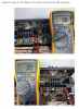
With the DVM + lead on the Base of TR708 and the - lead on E:
On the V scale I read 15.32vdc and the relay is off
On the mv scale the relay coil becomes active
I can use the V and mv scale selector to act like a switch to turn the relay on and off.

FYI
the Emitter to E measures 15.84vdc

Seeking an idea of what is taking place?
 
Register to hide this ad
Meters internal resistance is lower in the mv range. When TR708 is biased " on " it provides the path for the relay to " set " .. So your meter in the mv range shorts out the C & E of TR708.
 
Last edited:
Meters internal resistance is lower in the mv range. When TR708 is biased " on " it provides the path for the relay to " set " .. So your meter in the mv range shorts out the C & E of TR708.
Thank you for the explanation and it helps greatly.
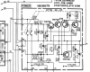
The schematic shows 12vdc Base, 12.5vdc Collector and 12.5vdc E which would close the relay? Thus the Base voltage would need to be at least 0.5vdc lower then the Collector and Emitter? The measurements taken do show the Base to be 0.5v less than the Emitter although the collector is at 0.00vdc.
 
Current configuration:

upload_2022-12-17_8-16-35.png

upload_2022-12-17_8-17-41.png

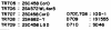
2SC458C - KSC1845F
2SA762WL4.5 - KSA992F
2SA682 O.Y - MJE253G
2SC458LGD - KSC1815
10D1 - EGP20B
1S1555 1N4148
SD-46 - EGP20B
 
The schematic shown in the prior post is from the CA-1000II Service Manual

This schematic is from the CA-1000 Service Manual


upload_2022-12-17_9-35-39.png

upload_2022-12-17_9-36-20.png

As seen throughout the boards and schematics the production date of the CA-1000 the actual boards are a hybrid.

I do find it most confusing that the power supply schematics are very much the same, the posted voltages don't match.
The relay voltages show the relay coil closing the contacts, yet the contacts are shown as open. From previous experience we have all found constant discrepancies in the published Yamaha documents. Is this the case here?
 
upload_2023-1-17_19-14-43.png
upload_2023-1-17_19-16-44.png
What I am trying to say with these statements is when I replace the outputs with 1N4148 as defined, then no voltage is present at the OUT, thus the relay will click?
With the 1N4148 in place is it possible to adjust Bias?
 
Last edited:
With the 1N4148 in place is it possible to adjust Bias?
So others don't waste their time...

The diodes are more for a fault finding exercise. You will be able to confirm that the driver base voltages do vary with VR and you will get a very minor increase in bias current, you won't(?) be able to set to 47mV/940mV if you can (*) then you must reset bias back to zero before installing outputs. The bias current mostly comes from the outputs c-e, ie, output Ic changes with Vce, Vc is fixed, Ve tied to Vb, and driver and VR.
(*) maybe fault situation?
 
Last edited:
So others don't waste their time...

The diodes are more for a fault finding exercise. You will be able to confirm that the driver base voltages do vary with VR and you will get a very minor increase in bias current, you won't(?) be able to set to 47mV/940mV if you can (*) then you must reset bias back to zero before installing outputs. The bias current mostly comes from the outputs c-e, ie, output Ic changes with Vce, Vc is fixed, Ve tied to Vb, and driver and VR.
(*) maybe fault situation?
You are much to kind! :)

I just pulled TR708 and it test fine, it is presently a JE253G

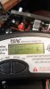
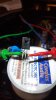
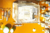
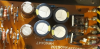
20230118_124909.jpg 20230118_125013.jpg 20230118_125150.jpg 20230118_125319.jpg
 
What I am trying to say with these statements is when I replace the outputs with 1N4148 as defined, then no voltage is present at the OUT, thus the relay will click?
Pulled all 4 outputs and inserted 1N4148 between b-e, no relay action.
 
Going round in circles? You reported TR708 b/c/e voltages, base and emitter were at spec however TR708c=0. Vc needs to be about 12Vdc.
The OUT pin (near 0Vdc) goes to the protect circuit who confirms all ok and then puts the required voltage on TR708b to operate the relay, but the relay does not operate because TR708 is either faulty or bad solder connection or burnt track or...
 
TR708 is either faulty or bad solder connection or burnt track or.
See above
EDIT:

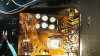
I show TR708 under test
I show the traces on the back side of the board - Don't see any issues.
I show all the different parts used on the top side of the board. That are new
I also define the use of the 1N4148 in place - thus no voltage on the outputs
 
Last edited:
Back
Top Bottom