• The move to the new server is done. There are some software and database maintenance updates in process. This has us passing the hat around to help out. We appreciate any donations. Seriously, even a dollar helps. The payment page may be found here - https://www.audiokarma.org/support.html

Yamaha CA-1000/CA1000II Power Supply and Protection Circuit Diagnostics, & Lower SNR values with the QA403

This post dates back to 2022?? I have been trying to follow the course of this, but I got lost a long time ago.. I thought it was just about measurements vs documentation but I guess the unit is not functioning.. maybe you just need to take it in to someone?? Hope it turns out for you. They're nice units when operating
It may also help to clarify that I have successfully conducted this work on ten different CA-1000's and they are all spread across this thread. So it not just the same unit over and over again.
 
It may also help to clarify that I have successfully conducted this work on ten different CA-1000's and they are all spread across this thread. So it not just the same unit over and over again.
Are you freaking kidding me !!!!!! :mad: I bet everyone trying to help think it just one unit !! Did you say this before somewhere? Because if you did I bet we all missed it .
 
  • Like
Reactions: mbz
Are you freaking kidding me !!!!!! :mad: I bet everyone trying to help think it just one unit !! Did you say this before somewhere? Because if you did I bet we all missed it .
I can absolutely guarantee that I am at fault somewhere along the line!
 
Need a better understanding of the protect circuit
Note the following,
- TR708 is for relay drive, need e-b current flow for relay to kick in
- TR709 is for control. It takes the results of the sensing transistors and sets/resets the relay drive TR. It also acts on the power on/off mute.
-TR705 and TR707 are for sensing (fault)
- L&R OUT pins connect to TR705e and TR707b (via some resistors)
- if the offset is more than -400mV to -500mV then TR705 turns on.
- if offset is more than +400mV to +500mV then TR707 turns on
- when either of these TR's turn on there is additional current flow from TR709b to TR707c/TR706e. This additional current flow lowers the voltage at TR709b to the point where it turns off, removing the current path for TR708e-b-... so it shuts down releasing the relay.

Your voltage measurements show an offset at about 15mV, insufficient to turn on sensing TR705,7.
TR709b (control) at 600mV should be ok, almost border line low, it's set by R716 and D710Vf.
So far everything looks ok.
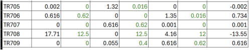
1729030028766.png

TR708e supply comes from halfwave rectified via D707, 14.6V is expected since no current flow/volt drop. It is actually 17.71 no voltage drop across R714
TR708b should be about 12V when current flowing and about 12.6V when no/little(leakage) current flow. It is actually 4.16
You have 1.14V makes me think TR708e-b has failed near open, diode check. Other alternative is TR709c-e open but would expect about 12V at collector in this case.

Earlier today the relay would react to the DMM probe touching TR709 c or e. it has now stopped doing that.

 
Last edited:
what is voltage on either side of R711( 10kohm) ? Want to see if voltage is on the outputs L and R .

Nashou
 
The heat on the outputs is inconsistent. One time I turn it on they heat up as expected in Class A & B. The next time I turn it on in Class B I have a very small amount of heat and in Class A they do become hot but lower.
 
The unit is running as per the calibration procedure with no signal input and no load on the outputs. It is on the variac at 117vac with Class A at 1.24amps and Class B at 0.64amps.
 
It just dawned on me that the bias on the outputs will effect the heat output. That 0.047 is based upon the original parts which have now been changed so the bias value may not be the same to operate correctly. Do I have that correct?
 
The best way to set bias is by measuring THD. If you don't have that capability, rule of thumb for most BJT class AB designs is 25 to 50 mA per output device. That translates into 5 to 10 mV for 0.22 Ohm emitter resistors. (2.5 to 5 mV - 0.10 Ohms, 7.5 to 15 mV - 0.33 Ohms, 10 to 20 mV - 0.47 Ohms). You will need to check the settings you made after a few minutes and keep an eye out for creeping bias. Make small adjustments at a time, sneaking up on the correct setting. Generally waiting 10-15 min with a load connected between adjustments will give you more stable readings. Always disconnect speakers or load when making adjustments. A final check after 30 min is advised. Aim for about 100 to 120 degrees F heatsink temps at idle (no music). Err on the lower end of that scale if the heatsinks are on the smaller side. A final check after 30 - 45 min with the cover back on is smart. Play some music and check heatsink temps one final time. You want to stay under 150 degrees F.

Some amps have switchable bias putting the output stage into a low power class A mode ie. NAD, Nakamichi, Luxman. Thats more of a gimmic in my opinion and just makes the amp run hotter with no benefit to sound. In most cases the amp doesn't have sufficient heatsinking to deal with the extra thermal load over longer periods of time and cooks your electrolytic caps, so I don't recommend using higher bias modes unless you can really detect a sonic benefit.

So basically speaking, going over the recommended bias range on a BJT class AB amp ends up in wasted heat and can make it unstable, creating a thermal instability problem, leading to overheating and also may increase THD. Staying in the 100 to 120 degree window of heatsink temps gives you long term stability and reliability and in most cases the best sound your amp is capable
 
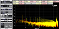
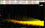
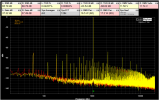
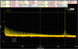
The only change in test parameters is the frequency generator.

Notice the difference in RMS Volts, THD

Question is this typical performance, also an explanation of the changes?


1729111578431.png

19khz
1729101858571.png

8.5k
1729102387641.png

24k
1729102449043.png

1k
1729111094118.png

1729112060080.png
 
Last edited:
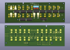
Decided to design and fabricated rear interface panel.

So many hours on this effort to upgrade parts and get the best possible signal into the front end of the preamp.

I believe this is revision 18 in this effort.

1000004008.jpg1000004012.jpg
 
Back
Top Bottom