• The move to the new server is done. There are some software and database maintenance updates in process. This has us passing the hat around to help out. We appreciate any donations. Seriously, even a dollar helps. The payment page may be found here - https://www.audiokarma.org/support.html

Yamaha CA-2010 stuck in protection help

quadmatrix82

AK Subscriber
Subscriber
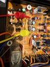
Hello Yamaha enthusiasts! I am in the process of repairing a Yamaha CA-2010 that I purchased DOA, upon inspection one of the filter caps had exploded, I proceeded with a full recap, clean up, new VD1212 diodes and all new transistors and diodes in the power supply, powering it up with a variac and dim bulb, the dim is bright immediately. I proceeded to disconnect the orange and blue wires to the amp modules, the dim is no longer bright however still stuck in protection.

I took some measurements at the power supply:
D418 -50v
D417 52v

+B2 28.5v
-B2 -28.5v
+b3 7.6v
-b1 -50v

Any suggestions where I can troubleshoot next? Thanks
 

Attachments

  • IMG_8471.jpeg
    IMG_8471.jpeg
    324.2 KB · Views: 17
Register to hide this ad
Amp in protection means either excessive dc voltage has been detected or failure in the protect circuit/psu.
OK you've disonnected the power however excessive voltage could be coming from front end.

Measure dc voltage at the LI(grey?) and RI(Violet?) pins/wires near the relay on the (underneath) power supply board, expect xxmV
 
Power on the amp, wait 10 seconds for voltages to stabilize then measure RI & LI should be mV
 
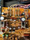
A clue perhaps? These two caps on the positive terminal have continuity to ground?? Confirmed they are the correct way around reviewing original photos and board orientation
 

Attachments

  • IMG_8511.jpeg
    IMG_8511.jpeg
    350 KB · Views: 12
I proceeded to disconnect the orange and blue wires to the amp modules,
The Blue and Orange wires are for the front end (differential pair...) power supply, so it's doubtful that you can get the amp to normalize. You need a working front end, resolder those wires and try one of the following,
1) disconnect the unregulated supply (larger red and white wires)
2) remove output transistors and replace one PNP,NPN pair with diodes placed between base and emitter pads, the diodes replicate the transistor b-e junction. Use 1N4148, 1N400X,,, for PNP cathode to base, for NPN anode to base
3) troubleshoot under DBT

Suggest try 1) then 3) then 2) if needed
 
Ok I will try removing the spade red white connectors to the amp module first and resolder the blue orange ones
 
The Blue and Orange wires are for the front end (differential pair...) power supply, so it's doubtful that you can get the amp to normalize. You need a working front end, resolder those wires and try one of the following,
1) disconnect the unregulated supply (larger red and white wires)
2) remove output transistors and replace one PNP,NPN pair with diodes placed between base and emitter pads, the diodes replicate the transistor b-e junction. Use 1N4148, 1N400X,,, for PNP cathode to base, for NPN anode to base
3) troubleshoot under DBT

Suggest try 1) then 3) then 2) if needed
Ok resoldered the orange and blue wires and disconnected the red and white ones - relay engages
 
OK what are the consequences if you reconnected the red&white wires then DBT'd powered up? Does anything melt? The purpose of the dbt is to prevent such melt so you can measure and work out what's going on.

Suggest remove red & white wires from one (working?) side so focus on faulty side.
Operations set to normal, vol=zero, coupler off
DBT power up
Measure Vdc at
- TP2
- +B(red)
- -B(white)
- D309 anode
- D310 cathode

You wont be able to do this in situ so you will need to jumper wires for the 4 psu wires and GND's, don't care about input or output
 
OK what are the consequences if you reconnected the red&white wires then DBT'd powered up? Does anything melt? The purpose of the dbt is to prevent such melt so you can measure and work out what's going on.

Suggest remove red & white wires from one (working?) side so focus on faulty side.
Operations set to normal, vol=zero, coupler off
DBT power up
Measure Vdc at
- TP2
- +B(red)
- -B(white)
- D309 anode
- D310 cathode

You wont be able to do this in situ so you will need to jumper wires for the 4 psu wires and GND's, don't care about input or output
Thankyou, no melt downs the dim lights up strongly instantly here are the results one channel connected
+b 7.75v
-b -7.5v
Tp2 5v
Hunting for the diode points will share them when I find them
 
Thankyou I will check them - outputs and drivers are new so I will check TR319
Is this D309/10
 

Attachments

  • IMG_0244.jpeg
    IMG_0244.jpeg
    266.2 KB · Views: 5
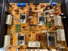
Here is my board - I have replaced the drivers and outputs already to combat this problem the symptom was the same however, some of the other transistors were also sub out
The outputs and drivers test good in circuit
Tested the fuse resistors again they seem good
 

Attachments

  • IMG_8550.jpeg
    IMG_8550.jpeg
    344.2 KB · Views: 5
Is this D309/10
The freely available sm is really bad. I should have said measure at TR319b but don't like probing transistors and figured a diode would be an easy find, my bad.

To make things worse, the board layout shows 2 of D910...

Suggest you download the CA-1010 sm, it is an easier read and there are some similiarities.

Can you measure Vdc at TR319b
 
The freely available sm is really bad. I should have said measure at TR319b but don't like probing transistors and figured a diode would be an easy find, my bad.

To make things worse, the board layout shows 2 of D910...

Suggest you download the CA-1010 sm, it is an easier read and there are some similiarities.

Can you measure Vdc at TR319b
This will be tricky to measure found the screw holding it a bit loose maybe not making contact to the board well enough? I tightened them all up to be sure and will try test it in circuit again first
 
Back
Top Bottom