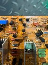
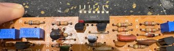
I can confirm it I will desolder the board and take a photo but it’s certainly like that


I can confirm it I will desolder the board and take a photo but it’s certainly like that

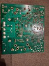
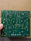
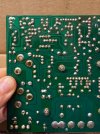
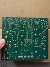
Thankyou I uploaded some additional photosFirst off always clean the solder side of the board your working on with Denatured alcohol so your able to see more clearly between
solder joints as the old solder flux and moisture barrier inhibits a clear view.
After you will be able to, and as will others via pics, if there is anything bridged or any cold solder joints.
Athanasios
Ok I had a look here are the measurements
+b 8v
-b -7.5v
Tp2 -4.5v
tr319b-3.1v
Tr319e -3.95v
Fr306 3.7v
tr320b -8v
These appear to be the last sensible suggestions.Standout is Q320b -8V abouts -B, -B1 rails.
Also voltage between Q319b and Q320b is 5V, target is 2.5V abouts.
Looks like a transistor on the -ve rail is flooding the output stage with -ve voltage.
Candidates are TR310 and TR318 and D308. Any of these parts not already replaced?
Measure TR310, TR318 b/c/e voltages and D308 anode/cathode, looking for standard Vbe=0.6V
and not Vce = Vce(sat). Also diode Vf(anode/cathode) = 0.6V
Confirmed no solder bridges that must be have been a bit of lint or tissue after cleaning the board.Photography is not great, assume you've inspected for solder bridges under magnifying lamp. Following looks iffy
I will check these, the board has all new diodes, transistors with the same fault as it had on first inspection. I also compared every resistor in circuit with good channel as another check and found nothing a miss.These appear to be the last sensible suggestions.
Maybe TR310 in saturation, measure b/c/e voltages
Maybe TR318 failing short c-e again b/c/e
Maybe D308 failing short, measure anode/cathode voltages (wont measure 0.6V)
Doubtful D304 open would cause, measure anode/cathode voltages
Yes.Is it possible the FET is problematic?