• The move to the new server is done. There are some software and database maintenance updates in process. This has us passing the hat around to help out. We appreciate any donations. Seriously, even a dollar helps. The payment page may be found here - https://www.audiokarma.org/support.html

Yamaha CA-2010 stuck in protection help

The freely available sm is really bad. I should have said measure at TR319b but don't like probing transistors and figured a diode would be an easy find, my bad.

To make things worse, the board layout shows 2 of D910...

Suggest you download the CA-1010 sm, it is an easier read and there are some similiarities.

Can you measure Vdc at TR319b
I could not access that point I removed the board and inspected all the joints and traces couldn’t find anything amiss. Tightened the screw, replaced all the diodes will board was apart and refitted. Now have about 650mv minimum on tp1 and tp2 the dim lights up very bright with no relay engaging confirmed outputs and drivers to be ok
 
Last edited:
I could not access that point
???
Can you identify TR319b?
Then flip over the board and look at the trackwork connected to TR319b, identify other components connected to this track/node.

Take a look at the schematic, you will see the following components connected to TR319b,
D309 anode
C310
R331
R329
TR312e
TR311c
C309
C308
R325

Measurement at any of these components on the same track is the same as measuring at TR319b or D309 anode.
For Rxxx and Cxxx components it's important to get the correct/connected end of the component to the track.

OK so you've changed some parts, dbt still bright, no relay click
measure
+B
-B
TP2
D314 anode/TR319e/R343/R345 node
TR319b (as above)
FR306/R344/R346/TR320e shared node/track
D310cathode/TR320b/D313anode/.... track
 
Last edited:
???
Can you identify TR319b?
Then flip over the board and look at the trackwork connected to TR319b, identify other components connected to this track/node.

Take a look at the schematic, you will see the following components connected to TR319b,
D309 anode
C310
R331
R329
TR312e
TR311c
C309
C308
R325

Measurement at any of these components on the same track is the same as measuring at TR319b or D309 anode.
For Rxxx and Cxxx components it's important to get the correct/connected end of the component to the track.

OK so you've changed some parts, dbt still bright, no relay click
measure
+B
-B
TP2
D314 anode/TR319e/R343/R345 node
TR319b (as above)
FR306/R344/R346/TR320e shared node/track
D310cathode/TR320b/D313anode/.... track
Ok I had a look here are the measurements
+b 8v
-b -7.5v
Tp2 -4.5v
tr319b-3.1v
Tr319e -3.95v
Fr306 3.7v
tr320b -8v
 
  • Like
Reactions: mbz
Standout is Q320b -8V abouts -B, -B1 rails.
Also voltage between Q319b and Q320b is 5V, target is 2.5V abouts.

Looks like a transistor on the -ve rail is flooding the output stage with -ve voltage.
Candidates are TR310 and TR318 and D308. Any of these parts not already replaced?

Measure TR310, TR318 b/c/e voltages and D308 anode/cathode, looking for standard Vbe=0.6V
and not Vce = Vce(sat). Also diode Vf(anode/cathode) = 0.6V
 
Standout is Q320b -8V abouts -B, -B1 rails.
Also voltage between Q319b and Q320b is 5V, target is 2.5V abouts.

Looks like a transistor on the -ve rail is flooding the output stage with -ve voltage.
Candidates are TR310 and TR318 and D308. Any of these parts not already replaced?

Measure TR310, TR318 b/c/e voltages and D308 anode/cathode, looking for standard Vbe=0.6V
and not Vce = Vce(sat). Also diode Vf(anode/cathode) = 0.6V
will check these and report the findings,
All the transistors and diodes were replaced
TR310 with MJE15032G
TR318 with KSC1845
D308 with 1n4007
 
Case is live, mica in good condition, check case to heatsink resistance
I don’t think tr10,9,19,20 had mica insulators? There is continuity to the heatsink and collector middle pin? Removing the originals I didn’t see a mica?
 
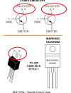
MJE15032G datasheet shows case/tab is live(= collector), mica or similiar required
The original 2sc1624 is also live to collector and doesn’t have a mica, why does the mje need one? The other working channel also doesn’t have a mica whilst fitted with the original components?
 
Assume nothing, google "mje15033 datasheet"


Indicates you have not checked the datasheets, like it takes 2 minutes...
I did check it looks like there are two boards for the Yamaha ca-2010 one seems to have the mica one doesn’t with these components mounted in different locations
 
I did check it looks like there are two boards for the Yamaha ca-2010
It's got nothing to do with what boards are in the CA-2010.
It's got 50% to do with the transistor datasheet and the other 50% with whether a heatsink is used.

Check the datasheet for the OEM part, you will see that the tab is NOT live/collector. You have (for whatever reason) replaced it with the MJE where the tab also acts as the collector. In this case you need mica.
 
It's got nothing to do with what boards are in the CA-2010.
It's got 50% to do with the transistor datasheet and the other 50% with whether a heatsink is used.

Check the datasheet for the OEM part, you will see that the tab is NOT live/collector. You have (for whatever reason) replaced it with the MJE where the tab also acts as the collector. In this case you need mica.
I refitted the originals and tested they still are ok first

Upon a test with the originals transistors here are the measurements I found
+b 10.2v
-b -10.2v
Tp2 -250mv
tr319b +1.5v
Tr319e -9.8v
Fr306 -8.8v
tr320b -3.3v

Bias and offset trimmers to minimum ccw position
 
The original 2sc1624 is also live to collector and doesn’t have a mica, why does the mje need one? The other working channel also doesn’t have a mica whilst fitted with the original components?
Extract of datasheet below. Pay attention to the "4", it can act as the collector, note the 4 is the metal tab.

The OEM part does not have a "4" on the tab

Upon a test with the originals transistors here are the measurements I found
Suspect one of the replacements are faulty.

Wasting my time explaining all this, fit the mica
 

Attachments

  • MJE.png
    MJE.png
    36.5 KB · Views: 3
Ooooops, I might have spoken too fast,
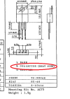
extract of 2SC1625 attached, note the reference to heat sink

If the transistor is fitted to a heatsink and the metal tab is live then you need mica.
 

Attachments

  • 2SC1625.png
    2SC1625.png
    65.5 KB · Views: 6
Ooooops, I might have spoken too fast,
extract of 2SC1625 attached, note the reference to heat sink

If the transistor is fitted to a heatsink and the metal tab is live then you need mica.
Ok Thankyou, I will try this but as I said above I don’t understand why with the original 2sc1624 on the working channel has no mica, and the other restoration threads for this model do not show it in photos nor does the sub either hence the confusion on my end.
 
OK, I failed to state the obvious.
Mica is only required if the heat sink is grounded.
I'd be against live heatsinks but then again the tech should be exercising due care.

Best someone else works with you.
 
Trying to wrap this up for me...

While the freely available sm is not great it appears to show TR310c is via metal tab and screw so in this case mica should not be used. You should inspect the trackwork and confirm this.
 
Trying to wrap this up for me...

While the freely available sm is not great it appears to show TR310c is via metal tab and screw so in this case mica should not be used. You should inspect the trackwork and confirm this.
I can confirm it I will desolder the board and take a photo but it’s certainly like that
 
Back
Top Bottom