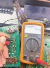
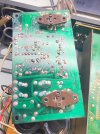
• The move to the new server is done. There are some software and database maintenance updates in process. This has us passing the hat around to help out. We appreciate any donations. Seriously, even a dollar helps. The payment page may be found here - https://www.audiokarma.org/support.html

Yamaha CA 600 Repair 2026

The bad news is the DBT still goes on just as soon as I plug the metal can output transistors in. It starts out kind of bright but as soon as I install the 2 screws holding down the transistors the bulb gets a little brighter.
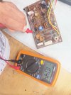
Flirting with disaster if you are plugging in and installing the TO-3 output transistors with power applied.
 
So someone replaced the LG's but got the pinout wrong with the replacement

What voltage are you seeing at R651 (red), +1.2V
R637 (blue) +0.6V
R639 (green) -0.6V
C621 (purple) -1.2V
Yes, the 2SC458's were the round with a flat face style, not the doghouse style and they were facing down.

Here are the readings of the right board
RED 1.4
BLUE 1.0
GREEN -.08
PURPLE -1.4

Here are the readings on the left board
RED -19.1
BLUE -19.8
GREEN -34.8
PURPLE -21.0

Please keep in mind that I do not know what the hell I am doing so I am providing one photo of the MultiMeter I am using so you can see the style and scale I used. The probe in the photo is testing the R637 Blue reading.
 

Attachments

  • e28358a0-5bac-45a7-8dcb-780edc4cd6d1.jpg
    e28358a0-5bac-45a7-8dcb-780edc4cd6d1.jpg
    125.7 KB · Views: 78
  • Like
Reactions: mbz
How is this boards Ground connected to the rest of the unit?

Unless its hidden under the Yellow and Red/White wires.


e28358a0-5bac-45a7-8dcb-780edc4cd6d1-jpg.3838405


having said that seems the right board looks ok. Have to
diagnose the left board.

Lets see if the DBT lights bright with the fuses removed from the left board.

And remember as Avionic stated never instal parts while the unit is energized.


Athaansios
 
  • Like
Reactions: mbz
How is this boards Ground connected to the rest of the unit?

Unless its hidden under the Yellow and Red/White wires.

And remember as Avionic stated never instal parts while the unit is energized.
Correct - when I put the cans in and took them out I shut the power and the DBT off. Do I need to redo the readings with the board grounded?

Transistors TR611 and TR609 get warm when the cans are in so all the readings were taken with cans removed. My wife has nice cans.

If I remove the fuses from any of the two boards the DBT will not light up. The fuses and the Can Output Transistors have to be installed to get the DBT to light up.


I will also go back to the function and Power Supply boards and make sure those transistors were installed correctly but I am pretty sure they were. Avionic and MBZ you will recall this whole ordeal started with the bridge rectifier on the Capacitor board being bad, in a different thread.
 
I would check to see if the cans are bad.

If you have any 470-560 ohm resistors sitting around of at least 1/2 watt you can use them instead of the cans to protect them form getting fried.
you put the resistor between the Emitter and base sockets for the cans. Being careful not to short the leads to the heat sink. use insulating heat shrink or something similar . This way you can see if bias adjustment and voltages are stable with out risking the output cans as you call them ;)
 
  • Like
Reactions: mbz
The metal can output are brand new from Mouser. If you recall I received them 10 days ago. They were never installed while the DBT was bright for longer than 20 seconds or so.
 
The metal can output are brand new from Mouser. If you recall I received them 10 days ago. They were never installed while the DBT was bright for longer than 20 seconds or so.
Ok then maybe use the resistor test for the rest of the repair just to err on the side of caution.

In the mean time look for solder bridges on the left board or any broken traces etc.
 
I want to check all the transistors on the Power Supply Board and the Function Board.

I pulled up the schematic but it is too small and I can not see the arrows to mark the Emitter pins on all the transistors.

The schematic of the Main Amp Board that you guys posted earlier was easier to see and read. I assume you are not using HFI Engine?

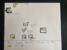
See the attachment for my emitter locations. Again this is a mirror of the Service Manual Picture. The green high lighted ones are the Emitter from what I can see. On the right side is where all the wires are soldered on.

The one that I am struggling with is TR702
 

Attachments

  • 36b0bb43-8133-4dc4-8b5c-0492330e0db7.jpg
    36b0bb43-8133-4dc4-8b5c-0492330e0db7.jpg
    77.6 KB · Views: 4
Last edited:
I want to check all the transistors on the Power Supply Board and the Function Board.

I pulled up the schematic but it is too small and I can not see the arrows to mark the Emitter pins on all the transistors.

The schematic of the Main Amp Board that you guys posted earlier was easier to see and read. I assume you are not using HFI Engine?

See the attachment for my emitter locations. Again this is a mirror of the Service Manual Picture. The green high lighted ones are the Emitter from what I can see. On the right side is where all the wires are soldered on.

The one that I am struggling with is TR702
forget the PS board for now and do what mbz asks below.
Clearly a problem with left power amp.

Diode test TR611
Measure Vdc at TP1 then repeat for TP3


Athanasios
 
forget the PS board for now and do what mbz asks below.
Too late, I checked all the trans on the PSB and they are all good.

I don't know what Diode Testing an transistor is and I could not find anything about it on Youtube to show me how. Does it need to come out of the board?

Also I know where TP1 (test point one) and TP2 but I do not know where TP3 is and can not find it in the schematic.

Am I measuring TP1 with the negative probe grounded to the chassis and the positive probe on TP1 ?
 
Last edited:
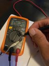
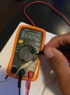
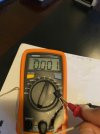
Like this?

First two pics are Neg on the emitter and last two are Pos on the emitter.


Also I know where TP1 (test point one) and TP2 but I do not know where TP3 is and can not find it in the schematic.

Am I measuring TP1 with the negative probe grounded to the chassis and the positive probe on TP1 ?
 

Attachments

  • 191c3b69-38c6-47d0-9c60-4dd214a23d22.jpg
    191c3b69-38c6-47d0-9c60-4dd214a23d22.jpg
    72.9 KB · Views: 12
  • a5c4ba2f-8c5a-4dcf-9c82-ae1d579f0854.jpg
    a5c4ba2f-8c5a-4dcf-9c82-ae1d579f0854.jpg
    67.8 KB · Views: 12
  • 2367b153-85c3-4b78-a76e-123b3a1f1203.jpg
    2367b153-85c3-4b78-a76e-123b3a1f1203.jpg
    74.2 KB · Views: 9
  • 74704543-4a92-48df-8edd-98598a57a71b.jpg
    74704543-4a92-48df-8edd-98598a57a71b.jpg
    67.9 KB · Views: 12
Is it strange that when I check for continuity between the Collector and Base of the TR611 transistor on the solder side of the board that I get a connection? Because of the glare it is hard to tell but the meter reads 2.0. Also I tried to take the pic with one hand but the first time I tested it, it was with both hands the the probe tips were not touching.

Also here is a pic of the board and I see no solder blobs or run off.
 

Attachments

  • b3aad712-6ced-434d-bb53-0dd0f2f91636.jpg
    b3aad712-6ced-434d-bb53-0dd0f2f91636.jpg
    116.6 KB · Views: 4
  • b3f63a67-85e5-4ac0-95ae-6881beda4760.jpg
    b3f63a67-85e5-4ac0-95ae-6881beda4760.jpg
    137.4 KB · Views: 3
Like this?

First two pics are Neg on the emitter and last two are Pos on the emitter.


Also I know where TP1 (test point one) and TP2 but I do not know where TP3 is and can not find it in the schematic.

Am I measuring TP1 with the negative probe grounded to the chassis and the positive probe on TP1 ?
there should be no shorts , looks like you have two shorts.

Also if you look at the diagram for testing you'll see some lines are black and red, that designates the probe color for testing, it needs to be done both way.s but once you find a short that transistor is bad.
 
  • Like
Reactions: mbz
Once again I assumed when I removed the factory transistors that they were installed correct, but obviously some were not.

I just looked at the Function Circuit Board and it looks like I have a **** of a mess. I need to sort the whole board out and it has 8 transistors and it looks like 4 are wrong. I can not find a pic of that board on line and see the direction that the original transistor are oriented and I will need to order more transistors.


6 of the 8 Transistors in the function Circuit Board were in wrong. I now have all 8 with their Emitters soldered in the Arrow schematic on the boards. This board is directly wired to the 2 Main Amp Boards that I have been working on for the past 3 weeks. Once again I put the new transistor in the same direction the old ones came out because all 8 were ECB transistors and because I did not know any better.
 
Last edited:
Once again I assumed when I removed the factory transistors that they were installed correct, but obviously some were not.

I just looked at the Function Circuit Board and it looks like I have a **** of a mess. I need to sort the whole board out and it has 8 transistors and it looks like 4 are wrong. I can not find a pic of that board on line and see the direction that the original transistor are oriented and I will need to order more transistors.
Was this amp worked on before? The factory hardly ever makes mistakes, having said that sometimes the schematics are wrong and or the silk screen on the boards are wrong.
But not knowing the providence of this unit before you got it its hard to say.

Dont jump around to other boards. keep everyone where either it and work on the left amp board as it seems to be the issue.

You dont need a pic, you just have to learn to read schematics and board layouts.

You'll get there :thumbsup:
 
  • Like
Reactions: mbz
Was this amp worked on before? The factory hardly ever makes mistakes, having said that sometimes the schematics are wrong and or the silk screen on the boards are wrong.
But not knowing the providence of this unit before you got it its hard to say.
It had to of been because some transistors were not the factory ones and some were installed wrong.

All boards are good now. Once again this board directly few the Main Amp Boards.

You are correct I don't need a pic but as you said sometime the schematics are wrong which I assume is very rare and I had no professional training in electronics repair. Everything else I worked on I removed the old, checked the PINOUTS and installed the new and was good.

If I were repairing this for a customer his bill would be about $8,000 by now.

Did anyone read in post #84 what I said about my wifes cans? What the hell is wrong with you guys?
 
Also I know where TP1 (test point one) and TP2 but I do not know where TP3
Fat fingers, I meant TP2, apologies

RED -19.1 = TR609b
BLUE -19.8 = TR609e
GREEN -34.8 = TR611e
PURPLE -21.0 = TR611b

I just looked at the Function Circuit Board
Dont jump around to other boards.
+1 Sort out the DBT issue, left power amp, replace TR611 which shows shorts
The function board is for the phono stage, don't bother looking at it until basic amp is working.

Don't panic. The factory often use different transistors than those listed in the sm. @avionic has already mentioned that TR607 was originally 2SC458LG, schematic shows 2SC458 hfe C or D. The LG is an improvement.
 
Back
Top Bottom