• Please note that Audiokarma will be offline briefly for updates early on Monday morning, September 28th.

Yamaha CA 600 Repair 2026

OK, is everyone sitting down? Because you guys are going to kill me.

Once again I am waiting on the parts so I am double the triple checking my previous work although you guys don't want me doing that.

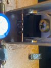
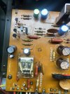
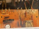
Here is a pic of a factory power supply board and 3 pics of all the different transistors on my PSB. Please tell me if you see a problem?

The last pic indicates I need to replace that resistor???
 

Attachments

  • Factory Board untouched.jpg
    Factory Board untouched.jpg
    146.3 KB · Views: 34
  • TR701.jpg
    TR701.jpg
    102.7 KB · Views: 30
  • TR702.jpg
    TR702.jpg
    81.4 KB · Views: 24
  • TR704.jpg
    TR704.jpg
    122.3 KB · Views: 24
  • 5d33cc2a-458f-4c18-b8e7-2105c6c3f4ab.jpg
    5d33cc2a-458f-4c18-b8e7-2105c6c3f4ab.jpg
    122.8 KB · Views: 32
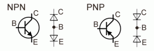
You have your KSC1845's wrong, those parts are ECB the holes are BCE, you need to flip them , the MJE350 is correct .

Once again learn the symbolism for the transistors Emitter collector and base symbol, I would re check every single TO92 you installed and for that matter any transistor you installed.

You need to get a parts tester to help you know what pin is E, B or C ... after many time doing it you get to know it by heart.

Hopefully those 1845's are still good and not fried.

55538645386_cbef194442_b.jpg


Athanasios
 
So I guessing that the originals I took out were 2SC458's in a X-172 package. They were facing the same direction as the KSC1845's I have installed and the slant was on the back side of the writing. So You are telling me that the C458's I removed were facing the wrong way or are you telling me the C458's front is the slant side with no writing on it.

I was told the writing was always on the front side of the Transistor and that is how you read it's pinout, with pins pointing down to identify ECB.

I have been checking all my work and finding problems, thats why I was checking it all. I have new KSC1845's that I will install.

And what about TR701 ???
 
Last edited:
So I guessing that the originals I took out were 2SC458's in a X-172 package. They were facing the same direction as the KSC1845's I have installed and the slant was on the back side of the writing. So You are telling me that the C458's I removed were facing the wrong way or are you telling me the C458's front is the slant side with no writing on it.

I was told the writing was always on the front side of the Transistor and that is how you read it's pinout, with pins pointing down to identify ECB.

I have been checking all my work and finding problems, thats why I was checking it all. I have new KSC1845's that I will install.

And what about TR701 ???
NO, Not all transistors are made the same , this is why you need to find the data sheets .

9tULFjd.jpg
 
There are transistors that do not have a collector in the middle. Therefore, buy a transistor tester that will show you the pin layout of any transistor and not only that.
Pavel;)
 
There is so much research in this hobby that I don't see how a professional makes any money on it. I bet a repairman always has more hours wrapped up in the repair than he can charge. This is absolutely nuts.

PS Nashua(666) - I turned TR701 around because I think it was the wrong way too.
Not ok, suggests you have a b-e short at TR611, remeasure. Wanting a 0.6V difference between b&e like TR609.

Now that the PSB should be correct with new transistors, I re-ran the tests on the left board again.

Red 1.54
Blue 0.97
Green -0.23
Purple -0.8


EDIT - I got the new transistors in the mail today and installed it. Hooked things back up and turned the unit on and got the DBT as soon as I installed the metal can output transistors and fuses in the right board. (note I barrowed the right transistor the other day and installed in the left board).

I was able to make the DBT go off by adjusting VR 602

I repeated the test on the right board and got the following.

Red 1.4
Blue 0.81
Green -0.49
Purple -1.0

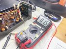
I took a reading at TP1 and got 0.15
I took a reading at TP2 and got 0.26
I took a reading between TP 1 & 2 and got 0.10

OK Now What?
 
Last edited:
I set the Mid Point voltage and bias. All seams like it went well.

Now what???
Id go to full power if you were able to make those adjustments.

you did follow the set up for making this adjustments, No load, no speakers, and Pre/amp coupler off correct?

have the meter on the Bias point when you turn it on and be ready to make adjustments to it.

Good luck.
 
Id go to full power if you were able to make those adjustments.

I apologize Nash, but I am not sure what you mean by Go To Full Power.

I did mid point and Bias according to the direction including powering up the amp for 3 minutes before starting. I was happy to see nothing got warm.

Back off the bias to a few mV or even 0mV then power up without DBT then readjust bias and offset then have a listen

MBZ - I'm going to need more information than that. You boyz keep forgetting all of this is first time for me. Please, a little more detail?


Also I was using the meter that doesn't have the scales on it so I went back and redid everything with the Flute type meter with mV on it. I think I got the left side dialed in but the right Midpoint just bounces all over the place and I can't even get it to Zero. I plugged in the speakers and turned the PreOut couple back on and the replay is not kicking in and no sound.
 
Last edited:
I set the Mid Point voltage and bias.
I assume you did this while on DBT, a common mistake. If you did this then connect to full mains power then the amp will be excessively biased possibly doing damage. Suggest the following,
- while on DBT set bias to near 0mV (0-2mV?)
- disconnect DBT then power up CA-600 using mains only
- set mid point and bias on both channels as per spec/service manual

the right Midpoint just bounces all over the place and I can't even get it to Zero
Mid point probably will drift a little, drift within +/-10mV is ok. I'd be concerned if it was within +/-20mV or higher.

I plugged in the speakers and turned the PreOut couple back on and the replay is not kicking in and no sound.
What dc voltages are you seeing on the L&R power amp boards at the O(ut) pins
 
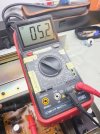
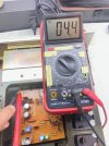
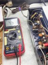
Now that I think the Power Supply Board is good I ran the voltages to make sure we are good. I disconnected the two chipped or burned resistors and ran an ohm test on both and got 4.4 and 5.2 on them. See Photos.

I ran voltage readings to all the wires coming off of the PSB and wrote them down on the photo below.

Hang tight more to come.
 

Attachments

  • b88c9eba-d13a-4070-bd01-ea5f1b66ee1d.jpg
    b88c9eba-d13a-4070-bd01-ea5f1b66ee1d.jpg
    120.3 KB · Views: 4
  • 4220da1e-0af5-4fa4-806d-99ca77376d76.jpg
    4220da1e-0af5-4fa4-806d-99ca77376d76.jpg
    118.8 KB · Views: 4
  • 59a1a056-2213-4567-8f69-136d84399f11.jpg
    59a1a056-2213-4567-8f69-136d84399f11.jpg
    114.5 KB · Views: 4
I re-ran the board voltages that we talked about earlier. Please look closely at the pics to make sure I used the correct scale.

On the left board I got the following.
Red .60
Blue -.56
Green -115
Purple 1.17

On the right board I got.
Red .21
Blue -.52
Green -1.02
Purple .76

Hang On - Even More to come.
 

Attachments

  • f3b5d512-c380-48cc-b71e-b642e14dc012.jpg
    f3b5d512-c380-48cc-b71e-b642e14dc012.jpg
    142.9 KB · Views: 2
I re ran the Midpoint voltage adjustment on both amps. See the pics below to make sure I used the correct scale on the multimeter. Once again this is with the DBT on and the power on to the amp.

I got the Left Midpoint to 0 and the Bias to 45mV if I did it right.

I got the right Midpoint to 1.5mV and the Bias to 46.2mV


I know what you are thinking but I am not comfortable going any further and without the DBT hooked up with good clear accurate directions on how to proceed. I have come too far and did way too much work to totally screw this all up now. Maybe I should just take it to a shop for the rest of the work? You can tell by the stupid little yellow notes on my multimeter that I really don't know what the hell I am doing and I am in way too deep. I can fix anything mechanical just by taking it apart and looking at it but I have absolutely not one hour of electronics repair training. The fact that I got this far is nothing short if a miracle and obviously I could not of done it without your help and countless hours of researching every little thing you told me to do.

If I am to continue I need to watch a video for each process that needs to be done.
 

Attachments

  • 7ed1b55c-d6a2-41d3-89ce-07fcfa59c367.jpg
    7ed1b55c-d6a2-41d3-89ce-07fcfa59c367.jpg
    158 KB · Views: 6
  • 8e50a4da-9ab2-420a-8f04-13e1f79991c6.jpg
    8e50a4da-9ab2-420a-8f04-13e1f79991c6.jpg
    142.2 KB · Views: 5
  • 52e4d88b-208d-448f-b4ca-c26e90b2352a.jpg
    52e4d88b-208d-448f-b4ca-c26e90b2352a.jpg
    149.9 KB · Views: 6
  • cb770e1e-fb95-4608-a575-f8978156126e.jpg
    cb770e1e-fb95-4608-a575-f8978156126e.jpg
    136 KB · Views: 5
Last edited:
You are almost there !!! :D, if you can set those point on DBT your ready to go to no DBT, but
first .......

Do as MBZ said, while on DBT set the bias to 0 , not the 47mV .

Now plug the amp to the regular wall socket with no DBT .

Now set the bias and Mid point as you did when it was on DBT , Bias to 47mV
and midpoint to 0 .

Athanasios
 
You mean -1.15 right?
Yes, that is correct. Sorry too many damn numbers floating around.
You are almost there !!! :D, if you can set those point on DBT your ready to go to no DBT, but
first .......
Reset Bias as close to Zero as I could get it, plugged the amp into a wall outlet and repeated the Mid Point and Bias settings.

Got both Midpoints to Zero and both Biases in the 47ma zone.


I powered the unit off and waited a minute. Flipped it on it's side and turned it back on to see if the replay would move and it did not.
 
Back
Top Bottom