• Please note that Audiokarma will be offline briefly for updates early on Monday morning, September 28th.

Yamaha CA 600 Repair 2026

Yes, that is correct. Sorry too many damn numbers floating around.

Reset Bias as close to Zero as I could get it, plugged the amp into a wall outlet and repeated the Mid Point and Bias settings.

Got both Midpoints to Zero and both Biases in the 47ma zone.


I powered the unit off and waited a minute. Flipped it on it's side and turned it back on to see if the replay would move and it did not.
So the relay has not clicked? Might be an issue with he protection circuit on the Power board .

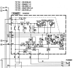
Is there the 12 volt at the Relay RY701 coils , you can check there or at the collector of TR704
1790280213357.png
 
  • Like
Reactions: mbz
Also check TR703b, expecting +0.6Vdc abouts
Test F702(3.9ohms)
C701(220/25V), C706(46/16V), C709?(1/50V) "should" have been replaced as pre-emptive maintenance
 
So the relay has not clicked? Might be an issue with he protection circuit on the Power board .

Is there the 12 volt at the Relay RY701 coils , you can check there or at the collector of TR704
I believe the relay coils are the back two pins opposite the end of the contacts and I do not have voltage there or at the TR704 Trans Collector. I removed the replay a few months back and cleaned the contacts and tested the coil with a 9 volt battery and it was working fine.
Also check TR703b, expecting +0.6Vdc abouts
Test F702(3.9ohms)
C701(220/25V), C706(46/16V), C709?(1/50V) "should" have been replaced as pre-emptive maintenance
TR703 base is reading Zero
In my pics yesterday I had removed one end of FR701 and FR702 and ran resistance tests on them. They were 4.4 and 5.2 ohms.

There are a total of 8 Capacitors on the PSB, I replaced the 5 polarized ones. C709 C710 and C711 were not changed because they are non polarized and I did not know how to order then. I can remove them from the board and test them?
 

Attachments

  • e5ee11f7-c6fb-4f60-a42c-87cc5778df86.jpg
    e5ee11f7-c6fb-4f60-a42c-87cc5778df86.jpg
    116.9 KB · Views: 8
Last edited:
I removed the 3 non polarized Capacitors and tested them with a MM. The largest on is supposed to be 100uf but it was reading 137uf??? I looked at the board with the thre non polarized Caps removed and for some reason C709 has a + on the board indicating it should be polarized yet it is not.

Please advise.
 

Attachments

  • 853ff441-c170-4587-a5b7-b867d9d53400.jpg
    853ff441-c170-4587-a5b7-b867d9d53400.jpg
    91.7 KB · Views: 3
  • e0eba3e4-0c12-442e-b274-863e846d99f4.jpg
    e0eba3e4-0c12-442e-b274-863e846d99f4.jpg
    124.5 KB · Views: 3
  • d4f2405a-c3ea-4b18-a246-3d20cbe43a2b.jpg
    d4f2405a-c3ea-4b18-a246-3d20cbe43a2b.jpg
    81.2 KB · Views: 3
TR703 base is reading Zero
Would have expected some xxxmV?
Anyway, TR703b needs to be about +0.6V(=ON). This will turn on TR704 and put the necessary 12V at TR704c.
TR705,6,7 need to be OFF. The "suck" additional current through R708(?) causing TR703b to drop/turn off.

F702, D703 provides the relay power to TR704e, also acts as AC-OFF detection
TR703 receives power from regulated supply D706 (21V zener) and R707,8.

At least 2 possibilities
D706 has failed short.
Very unlikely since would affect +50 supply
- measure Vdc one side of R707, expect about +20Vdc
- repeat on other side of R707, maybe +1V?
Another remote possibility is either TR705,6,7 has failed short or you have inserted with incorrect orientation

Start with R707 voltage measurements
 
for some reason C709 has a + on the board indicating it should be polarized yet it is not.
Don't loose sleep on it.
A non-polarized cap can replace a polarized cap however a polarized cap cannot replace a non-polarized.

A polarized cap must be biased in a particular way/direction. The -ve terminal must be lower than the +ve terminal voltage. For non-polarized caps either terminal can act as +ve/-ve
 
At least 2 possibilities
D706 has failed short.
Very unlikely since would affect +50 supply
- measure Vdc one side of R707, expect about +20Vdc
- repeat on other side of R707, maybe +1V?
Another remote possibility is either TR705,6,7 has failed short or you have inserted with incorrect orientation

Start with R707 voltage measurements
R707 is reading Zero at both ends.

TR705 and TR707 were just replaced with brand new and properly installed the other day.
TR706 is supposed to be a 2SA572 from factory with a ECB Pinout.
My TR706 that came out of my PSB was a 2SA763 also with an ECB Pinout.
I have a bunch of KSA992's on hand so I just installed a band new one for the hell of it.

I turned the amp back on and still not engagement from the Relay.
I checked for power at R707 again and this time I am reading power but it is 0.002 Vdc.

I tested the Zener Diodes and D706 and D705 both read 0.703 on the Diode Scale in the board.
D704 read 0.602 on the diode scale in the board.
D707 read 0.285 on the diode scale in the board.
D703 read 0.562 on the diode scale in the board, but this one does not look like the other Zener diodes.
 
Last edited:
R707 is reading Zero at both ends.
If you trace the connections on the schematic you will see that the bottom side of R707 connects to D706(z) cathode, there should be about +20Vdc at this point. Following possibilities,
- missing B+ rail, eg, failed rectifier, FR702 open
- D705(z) open
- D706 short
- burnt track

Suggest measure Vdc at the following on relay/power supply board,
- B+ (50V?)
-D705 cathode
- D705 anode

If D705 anode is about +20Vdc then with amp powered off/unplugged measure the resistance between D705 anode and one side of R707, repeat for other side of R707. Expect one measurement to be about 1ohm and 150kohms for the other
 
If you trace the connections on the schematic you will see that the bottom side of R707 connects to D706(z) cathode, there should be about +20Vdc at this point. Following possibilities,
- missing B+ rail, eg, failed rectifier, FR702
The Bridge Rectifier in the Electrolytic Supply board was changed a few months ago. It was the reason there was a fuse burning short in the first place.

Suggest measure Vdc at the following on relay/power supply board,
- B+ (50V?)
-D705 cathode
- D705 anode
All 8 relay solder points are dead, Zero Voltage
B+ is measuring .20 on a 20 volt DC scale, please see attached photo.
D705 Cathode = 1Vdc
D705 Anode = Zero 0

If D705 anode is about +20Vdc then with amp powered off/unplugged measure the resistance between D705 anode and one side of R707, repeat for other side of R707. Expect one measurement to be about 1ohm and 150kohms for the other
D705 only 0 volts.
D705 Anode to R707 = .26 M Ohms
D705 Cathode to R707 = 84.5 K Ohms

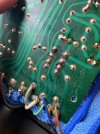
I see no issues with the traces on the PSB - Please see photo.

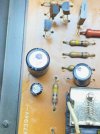
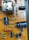
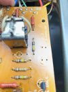
In the last photo those two resistors next to the relay are suspect. The leads on the black one are tarnished black and the leads on the Brown one look a little burnt???
 

Attachments

  • Relay.jpg
    Relay.jpg
    137.4 KB · Views: 6
  • RelaySolderPoints.jpg
    RelaySolderPoints.jpg
    151.4 KB · Views: 5
  • 451329e9-a7a9-4b47-87fe-881d9652dc4b.jpg
    451329e9-a7a9-4b47-87fe-881d9652dc4b.jpg
    129.4 KB · Views: 8
  • PowerSupplyBoard.jpg
    PowerSupplyBoard.jpg
    134.4 KB · Views: 7
  • 2BurntResistors.jpg
    2BurntResistors.jpg
    106.2 KB · Views: 6
Last edited:
Just for the hell of it as I mentioned earlier I put a brand new Bridge Rectifier in the Main Filter Caps Board. I took voltage measurements with the amp on.
ET Zero
+B 30Vdc
AC 24.6 Vac
-B -30 Vdc
ES Zero
E Zero at all 3 points.

Note there is a solder glob between ES and the first E.
I have attached a schematic but I can not tell if it is supposed to be there?
 

Attachments

  • f537557f-ebbc-405e-8ac6-38d6e76818e4.jpg
    f537557f-ebbc-405e-8ac6-38d6e76818e4.jpg
    115 KB · Views: 9
  • 1790459187867.png
    1790459187867.png
    240 KB · Views: 8
If D705 anode is about +20Vdc then with amp powered off/unplugged measure the resistance between D705 anode and one side of R707, repeat for other side of R707. Expect one measurement to be about 1ohm and 150kohms for the other
He asked to measure with power off, the resistance above ^^^
D705 only 0 volts.
D705 Anode to R707 = .26 M Ohms
D705 Cathode to R707 = 84.5 K Ohms
But here you measured wrong, you measured one end of R707 from the cathode of D705, it was suppose to be both measurements from the anode side of D705 to either side of R707.

NOTE : Also it be advised when ever working on these old units to clean off the solder side of the boards with Denatured alcohol and a tooth brush to remove all the old flux and moisture barrier they apply to it at the factory, it allows for you and others via pictures to have a nice clear look at all solder pads and traces.

Athanasios
 
Guys, plz keep in mind, I'm in a different time zone altogether, so if you see something anytime, always welcome to chime in, though this issue looks straight forward if OP took measurements with power on!!! Got a 1010 and a 1000ii(JDM) that are causing me some grief.
 
No.:biggrin: Just sippin whiskey and cranking some tunes.:biggrin: Adding to my post count. :thumbsup:

And doing a C-4 LED upgrade.
WOW you broke 88k in posts!!!


:D

Nashou
Guys, plz keep in mind, I'm in a different time zone altogether, so if you see something anytime, always welcome to chime in, though this issue looks straight forward if OP took measurements with power on!!! Got a 1010 and a 1000ii(JDM) that are causing me some grief.
Totally understood, I'm not even sure which time zone or area the OP is located.
Im guessing west coast USA?

Nashou
 
Back
Top Bottom