Se oye un chasquido al apagar el amplificador.
Intente poner el interruptor del acoplador trasero en apagado y luego vuelva a ejecutar la prueba, encienda la alimentación, cualquier chasquido al apagar, no espere nada.
¿Funciona la luz de encendido? Ayuda a reducir la carga del C714.
¿Has sustituido el amortiguador RC que va en paralelo al interruptor de encendido?
Sí, el CA-800 es un buen amplificador, pero es un engorro trabajar en él. El CA-1000 es un poco mejor. El CA-1010 y el CA-2010 tienen un sonido diferente, pero también son más fáciles de reparar; son buenos amplificadores. En general, los componentes separados de Yamaha son un paso más allá, por ejemplo, el C-??/M-??


You are using an out of date browser. It may not display this or other websites correctly.
You should upgrade or use an alternative browser.
You should upgrade or use an alternative browser.
Yamaha CA-800 protection relay not working
- Thread starter mikevinci
- Start date
Se oye un chasquido en la etapa del amplificador de potencia. Podría ser un problema con el relé, que no se abre lo suficientemente rápido.
¿Has aumentado el valor de C714? Debería ser de 220 µF o de 47 µF.
Pruebe D709 y luego R717, no debería fallar abierto
Consulte la página 11 del manual de servicio de la placa de circuito del interruptor de alimentación y los circuitos integrados C731 y C732; estos son los circuitos de amortiguación RC de esta placa.
Could this component be a good replacement for these shock absorbers?
I haven't done the power strip test yet, but it seems like an excellent way to rule things out. I'll do it as soon as I can and report the resultsNot sure the switch cap is faulty.
Connect amp to a power board then try powering off at the power board or wall switch not amp switch, do you still get a pop?
I'm installing the second power amplifier board I had pending, and I've run into a problem. I short-circuited the OUT and E pins of the board while taking measurements. The result was smoke, and I quickly shut it down. I found resistor 623 was visually damaged, although it measured fine, so I replaced it.
Now I have a voltage of 45V between OUT and E. Obviously, the relay doesn't activate when I connect this board.
Can you guide me on which component might be damaged? I've measured, but I can't identify which one it could be. Perhaps TR610 and TR611 are the candidates. I've broken them again, but I measured them on diode scale, and they measure correctly.
Oh my god, I have to be more careful. I'm not in this career to repair this unit or to cause problems. 
Now I have a voltage of 45V between OUT and E. Obviously, the relay doesn't activate when I connect this board.
Can you guide me on which component might be damaged? I've measured, but I can't identify which one it could be. Perhaps TR610 and TR611 are the candidates. I've broken them again, but I measured them on diode scale, and they measure correctly.
Oh my god, I have to be more careful. I'm not in this career to repair this unit or to cause problems.
On the other hand, during the power amplifier stage tests,( which only work with one channel),, I tried swapping the input cable from the right channel to the left to verify that the audio output on both channels was working.
Interestingly, I expected both to work, but they didn't; only one output worked. Both outputs measured the same, and I understand that even after swapping these cables (red and white shielded, two wires, live and ground) on the same board, it should have worked, but it didn't. In these tests, one of the stages was always disconnected.
Is this normal behavior? Or is there a problem with the audio on that channel despite both having the same output voltage to the power amplifier?
Is this unit so intelligent that it knows which channel each audio output to the power stage belongs to and doesn't allow them to be swapped?
Interestingly, I expected both to work, but they didn't; only one output worked. Both outputs measured the same, and I understand that even after swapping these cables (red and white shielded, two wires, live and ground) on the same board, it should have worked, but it didn't. In these tests, one of the stages was always disconnected.
Is this normal behavior? Or is there a problem with the audio on that channel despite both having the same output voltage to the power amplifier?
Is this unit so intelligent that it knows which channel each audio output to the power stage belongs to and doesn't allow them to be swapped?
Last edited:
Did the glass fuses F601 or F602 blow?I short-circuited the OUT and E pins
Candidates are TR610 and TR611 along with TR608 and TR609
Points to TR609I found resistor 623 was visually damaged
Some test points
D602 anode/TR608b +1.8Vdc
D607 anode/TR608e +1.2V
D607 cathode +0.6V
We have all done it, use minnigrabbers where possibleOh my god, I have to be more careful. I'm not in this career to repair this unit or to cause problems.
No, the unit is dumb, you can move the IN & E wires to the other channel, expect it to workIs this unit so intelligent that it knows which channel each audio output to the power stage belongs to and doesn't allow them to be swapped?
After connecting it for the first time, the F601 blew, it was replaced, and subsequently, while taking measurements, the OUT and E short circuit occurredDid the glass fuses F601 or F602 blow?
That's right, I don't have any of those. I need to get a game. I used crocodiles.Candidates are TR610 and TR611 along with TR608 and TR609
Points to TR609
Some test points
D602 anode/TR608b +1.8Vdc
D607 anode/TR608e +1.2V
D607 cathode +0.6V
I will check these transistors
We have all done it, use minnigrabbers where possible
I have a problem with this channel, and it's obvious that despite having the correct voltage compared to the other channel that was working, there's no audio. It's very strange, isn't it? It should be outputting audio, and I don't understand whyNo, the unit is dumb, you can move the IN & E wires to the other channel, expect it to work
Last edited:
Please correct me if I'm wrong
One power amp working, audio ok
Other power amp accidental short OUT pin and GND, need to test/identify failed parts.
The following may help identify failed parts
To test the preamp of the failed/short channel you moved the IN/E wires from this channel to the working power amp, you did not get audio, need to troubleshoot.
It would have been easire to switch the rear coupler off then using rca cables connect left pre-out to right main-in, likewise connect right pre-out to left main-in, ie, cross the channels.
Suggest go back to the volume board and check the white(L) and pink(R) wires for audio with your multimeter set to Vac, especially at the yellow wrapped wires to the filter board. The coupler switch has a history of being dirty causing lost channels.
One power amp working, audio ok
Other power amp accidental short OUT pin and GND, need to test/identify failed parts.
The following may help identify failed parts
Some test points
D602 anode/TR608b +1.8Vdc
D607 anode/TR608e +1.2V
D607 cathode +0.6V
To test the preamp of the failed/short channel you moved the IN/E wires from this channel to the working power amp, you did not get audio, need to troubleshoot.
It would have been easire to switch the rear coupler off then using rca cables connect left pre-out to right main-in, likewise connect right pre-out to left main-in, ie, cross the channels.
Suggest go back to the volume board and check the white(L) and pink(R) wires for audio with your multimeter set to Vac, especially at the yellow wrapped wires to the filter board. The coupler switch has a history of being dirty causing lost channels.
Después de conectarlo por primera vez, el F601 se quemó, fue reemplazado y posteriormente, mientras se tomaban mediciones, ocurrió un cortocircuito entre OUT y E.
Indeed, as you say, one side works fine and I can hear it when I connect the red audio cable to IN and EPor favor corrígeme si me equivoco.
Un amplificador de potencia funciona, el audio está bien.
En otros casos, un cortocircuito accidental entre el pin OUT y GND del amplificador de potencia requiere probar e identificar las piezas defectuosas.
Lo siguiente puede ayudar a identificar las piezas defectuosas.
Para probar el preamplificador del canal averiado/en cortocircuito, movió los cables IN/E de este canal al amplificador de potencia que funciona correctamente, pero no obtuvo audio; es necesario solucionar el problema.
Hubiera sido más fácil apagar el acoplador trasero y luego usar cables RCA para conectar la salida de preamplificador izquierda a la entrada principal derecha, y de igual manera conectar la salida de preamplificador derecha a la entrada principal izquierda, es decir, cruzar los canales.
Se recomienda revisar la placa de volumen y comprobar si hay señal de audio en los cables blanco (izquierdo) y rosa (derecho) con el multímetro configurado en Vac, especialmente en los cables amarillos que van a la placa de filtro. El interruptor de acoplamiento suele ensuciarse, lo que provoca la pérdida de canales.
correctPlease correct me if I'm wrong
One power amp working, audio ok
Other power amp accidental short OUT pin and GND, need to test/identify failed parts.
The following may help identify failed parts
To test the preamp of the failed/short channel you moved the IN/E wires from this channel to the working power amp, you did not get audio, need to troubleshoot.
That's correct, that's also good evidence, it makes you not know...
Only the audio IN and E on the red cable work.Suggest go back to the volume board and check the white(L) and pink(R) wires for audio with your multimeter set to Vac, especially at the yellow wrapped wires to the filter board. The coupler switch has a history of being dirty causing lost channels.
Last edited:
Please confirm if I have correctly identified the points on the actual plate.To confirm that these are the test points you indicated, I'm uploading some photos and the diagram showing where I believe they are
I've measured the candidate and non-candidate transistors, but they don't appear to have any problems. I suppose the fault will only manifest itself when they're under voltage
What bad luck, I practically had it done and now I'm crazy and lost again with this new breakdown.
Attachments
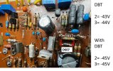
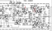

Correct, the tester is low voltage (8-9V??) the component may fail at higher voltages 50VdcI suppose the fault will only manifest itself when they're under voltage
Point 1,2,3 on schematic (puntos medicion) are correctPlease confirm if I have correctly identified the points on the actual plate.
Points 2,3 D607 is correct
Point 1 on D602 is incorrect, wanted anode but probably not significant.
Results point to failed TR611 or TR609.
Suggest remove outlet transistors TR610, TR611 then DBT power up and check voltage at the OUT wire
With Tr610 and Tr611 removed, it maintains an output voltage at OUT of -41v with DBTCorrect, the tester is low voltage (8-9V??) the component may fail at higher voltages 50Vdc
Point 1,2,3 on schematic (puntos medicion) are correct
Points 2,3 D607 is correct
Point 1 on D602 is incorrect, wanted anode but probably not significant.
Results point to failed TR611 or TR609.
Suggest remove outlet transistors TR610, TR611 then DBT power up and check voltage at the OUT wire
Does this indicate that Tr609 could be a candidate?
Given my doubts, I decided to replace all the diodes on the board just in case.
Could this test of removing the final transistors indicate that the source of the fault is TR609?
I don't have a 2SA706, and from what I've seen, it will be difficult and expensive to obtain. If this is the cause, would a good replacement be an MJE15033?
Last edited:
Outside chance it could be TR604 but more likely TR609 since it matches the stressed R623 when OUT was shorted to GND.With Tr610 and Tr611 removed, it maintains an output voltage at OUT of -41v with DBT
Suggest pull TR609 and connect whatever diode you have handy 1N4148 or 1N400x between base and emitter.
Connect anode to emitter and cathode to base solder pads then dbt power up and check OUT voltage. The diode replicates the transistor b-e junction.
Después de conectarlo por primera vez, el F601 se quemó, fue reemplazado y posteriormente, mientras se tomaban mediciones, ocurrió un cortocircuito entre OUT y E.
I used a 1N4004 anode emitter on TR609 and cathode on the base of TR609, resulting in -40vOutside chance it could be TR604 but more likely TR609 since it matches the stressed R623 when OUT was shorted to GND.
Suggest pull TR609 and connect whatever diode you have handy 1N4148 or 1N400x between base and emitter.
Connect anode to emitter and cathode to base solder pads then dbt power up and check OUT voltage. The diode replicates the transistor b-e junction.
So, can I try replacing TR604 and verifying the correct voltage? Can I keep the diode on TR609 for this test?I used a 1N4004 anode emitter on TR609 and cathode on the base of TR609, resulting in -40v
That's good news.I used a 1N4004 anode emitter on TR609 and cathode on the base of TR609, resulting in -40v
So outputs still removed, TR609 removed and replaced with 1N4004 between b-e.
Please diode test TR604, looking for c-e short,
Also measure Vdc at each wire A,B,C,S
Correct outputs are still withdrawn. and TR609 also retired.That's good news.
So outputs still removed, TR609 removed and replaced with 1N4004 between b-e.
Please diode test TR604, looking for c-e short,
Also measure Vdc at each wire A,B,C,S
Now do I have to put another diode equal to 1n4004 in TR604? emitter anode and cathode colector on tr604? is that so?
Last edited: