• The move to the new server is done. There are some software and database maintenance updates in process. This has us passing the hat around to help out. We appreciate any donations. Seriously, even a dollar helps. The payment page may be found here - https://www.audiokarma.org/support.html

Yamaha CA-800 protection relay not working

Now do I have to put another diode equal to 1n4004 in TR604
No. Test TR604 with your multimeter in diode test mode, see below.

Also measure Vdc at each wire A,B,C,S
Unlikely TR608 faulty, more likely TR604. Voltage measurement should confirm.

Also TR604 2SC1124 ebc replacement KSC2690 ecb so need to twist legs and insulate if replacement needed
 
I installed a KSC2690AY on TR604. I crossed the pins, leaving the base in the center; the diode on TR609 remains installed.

I'm still getting a reading of -34V
in OUT

Something curious happens: before installing it, I measure and identify the emitter (greatest voltage drop). Once installed, I measure it again, without tensión and the measurement indicates that the emitter and collector are reversed.

How is posible?

Furthermore, I've already damaged some of the traces on the back of the board. A disaster :eek:

In this situation I haven't tried adjusting VR601, could it be that VR601 is very, very out of adjustment?
 
Last edited:
Please measure the voltages at wires A,B,C,S Also measure voltage at D602 anode, you incorrectly gave me cathode.
 
Please measure the voltages at wires A,B,C,S Also measure voltage at D602 anode, you incorrectly gave me cathode.
At all points it measures -44v except for S which measures -39v
 

Attachments

  • D602.jpg
    D602.jpg
    113.8 KB · Views: 9
  • tr604.jpg
    tr604.jpg
    154.2 KB · Views: 8
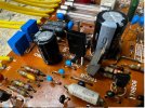
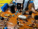
Appears you have incorrectly installed TR604(KSC2690) emitter leg should not be bent

edit Rotate 180degrees, front should facing those blue caps
 
Last edited:
Arrow shows front, leg closest electrlytic cap is emitter, needs to be straight. Only need to rotate the KSC2690
 

Attachments

  • resultados 607.jpg
    resultados 607.jpg
    123.9 KB · Views: 3
Arrow shows front, leg closest electrlytic cap is emitter, needs to be straight. Only need to rotate the KSC2690
Appears you have incorrectly installed TR604(KSC2690) emitter leg should not be bent

edit Rotate 180degrees, front should facing those blue caps
I rotated the KSC2690 180 degrees, the -41V persists at A B C S, the diode at TR609 remains and the final transistors are removed from the board.

Sorry, I made a mistake, it's -51V D602 anode too
 
Last edited:
  • Like
Reactions: mbz
TR604(KSC2690) orientation is correct, maybe it was damaged when inserted incorrectly??? Would not explain -51V at D602 anode.

edit with amp powered off measure resistance between D602 anode and -50 wire
Need to sign off...
 
La orientación del TR604 (KSC2690) es correcta, ¿quizás se dañó al insertarlo incorrectamente? Eso no explicaría los -51 V en el ánodo D602.

Edite con el amplificador apagado y mida la resistencia entre el ánodo D602 y el cable de -50.
Necesito cerrar

TR604(KSC2690) orientation is correct, maybe it was damaged when inserted incorrectly??? Would not explain -51V at D602 anode.

edit with amp powered off measure resistance between D602 anode and -50 wire
Need to sign off...
Okay, no problem.

Between anode D602 and -50v resistor of 15kΩ
 

Attachments

  • IMG_7505.jpeg
    IMG_7505.jpeg
    333 KB · Views: 13
Last edited:
Please measure dc voltage at TP1.

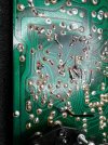
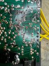
Yeah, board is a mess, you need to clean up the solder splatter, acetone or board cleaner and soft brush.
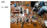
Arrow below is TR604e (-50V abouts) and R610 is a concern

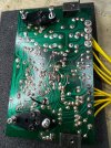
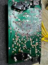
Best to post picture of entire board, solder side
 

Attachments

  • CA800tracks.jpeg
    CA800tracks.jpeg
    196.8 KB · Views: 8
Por favor, mida el voltaje de CC en TP1.

Sí, la placa está hecha un desastre, necesitas limpiar las salpicaduras de soldadura, acetona o limpiador de placas y un cepillo suave.
La flecha de abajo es TR604e (aproximadamente -50 V) y R610 es un problema.

Lo mejor es publicar una foto de toda la placa, lado de soldadura.
TP1 = +39,6 V
Desafortunadamente, es un desastre.

Pero la continuidad es correcta en las pistas, y no se detectó ningún cortocircuito en otras pistas, aunque con las uniones de soldadura en tan mal estado, es posible.

Buscaré alambre esmaltado del calibre adecuado y rehaceré las pistas dañadas para asegurarme.

Publicaré las fotos cuando esté terminado.
 

Attachments

  • IMG_7513.jpeg
    IMG_7513.jpeg
    384.5 KB · Views: 9
  • IMG_7512.jpeg
    IMG_7512.jpeg
    371.7 KB · Views: 8
  • IMG_7511.jpeg
    IMG_7511.jpeg
    359.7 KB · Views: 9
  • IMG_7510.jpeg
    IMG_7510.jpeg
    371.5 KB · Views: 8
  • IMG_7509.jpeg
    IMG_7509.jpeg
    347.4 KB · Views: 7
  • IMG_7508.jpeg
    IMG_7508.jpeg
    381.6 KB · Views: 6
  • IMG_7514.jpeg
    IMG_7514.jpeg
    310.8 KB · Views: 9
Last edited:
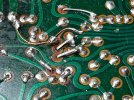
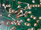
Please reflow 2 solder blobs marked in red.

With amp powered off measure resistance between D602 anode and -50 wire
Also measure TR604 b/c/e voltages to ground
Remeasure D602 anode voltage to GND
Please use black speaker connector as GND
 

Attachments

  • CA800_2.jpeg
    CA800_2.jpeg
    229.7 KB · Views: 8
Clean the entire board with IPA or acetone, then check all the tracks with an ohmmeter to make sure they are not touching adjacent tracks, etc. Then solder all the connections and clean all the soldering. Looking at your photos, it seems to me that there are shorts and cold joints.
Pavel;)
 
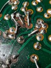
I finally found a fault. I meticulously checked all the solder points until I located a trace on the negative leg of capacitor C610 that had broken traces leading to R603 and to the emitter TR604.

I'll repair it tomorrow with care and attention. I'll also take measurements and report back. I hope this fixes the problem.

Could the short circuit be related to this fault I found? If so, clearly the short circuit wasn't the source of the problem, but rather something else, and perhaps it prevented damage to the final transistors. I don't know; I'll find out tomorrow.
 

Attachments

  • IMG_7511_1.jpg
    IMG_7511_1.jpg
    212.5 KB · Views: 6
  • IMG_7514_1.jpg
    IMG_7514_1.jpg
    177.7 KB · Views: 5
Last edited:
Hello, I repaired the broken solder joint.

I reinstalled transistor TR608 and removed the temporary diode.

When I connected the power stage to the unit along with the existing one, the protection circuit doesn't activate, and the relay clicks.

Apparently, the short circuit isn't showing up.

I am providing the measurement data obtained after the repair for your interpretation:

EQUIPMENT OFF
Anode resistance D602 and -50V -> 155 ohms

EQUIPMENT ON

TR604
GND/Base -> -54V
GND/Emitter -> -55V
GND/Collector -> -70mV

Anode D602/GND 0.6V
Cathode D602/GND 1.8V

GND/OUT -> 0.4V

GND/A -> 0.6V
GND/B -> 0.6V
GND/C -> 0.6V
GND/S -> 3.2V

TR608
GND/B -> -0.091V
GND/E -> -0.28V
GND/C -> -44.4V

+50V -> +55V
-50V -> -55V
-B -> -44V
+B -> +44V

I made the adjustments to the new stage according to the service manual, but I can't adjust the Class B bias to 0.047V; it only allows me to set it to 0.022V with the variable resistor fully extended at one end.

I haven't tested Class A yet; I don't want to get impatient in case there's a problem

I tried connecting Class B audio, and it sounds the same as before, but only on one channel
 
Last edited:
  • Like
Reactions: mbz
Back
Top Bottom