
Not really.. I'd be more concerned with measured DC voltage with a multimeter. I'm assuming your volts/div. is 5v per div. on the scope.. Can't tell by your photo.Any thoughts on these waveforms?


Not really.. I'd be more concerned with measured DC voltage with a multimeter. I'm assuming your volts/div. is 5v per div. on the scope.. Can't tell by your photo.Any thoughts on these waveforms?

Not really.. I'd be more concerned with measured DC voltage with a multimeter. I'm assuming your volts/div. is 5v per div. on the scope.. Can't tell by your photo.

These are actual measurements taken with a multimeter.
These are actual measurements taken with a multimeter.
At this point I have absolutely no confidence in the validity / accuracy of the published schematic.Without a CA-810 physically sitting in front of me.
Which make no sense at all.These are actual measurements taken with a multimeter.

PatricAnd what do you think about this :
https://www.grosfichiers.com/xBF6xnviRA6
you will download CA810 SM high definition scanned pages
I don't think you will find better than that anywhere on the web except on AK !

KEY WORD "EXAMPLE"18K
560 OHM
1,5 KOHM
No ?
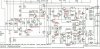
Honnêtement, je ne comprends pas pourquoi il est si compliqué pour vous de comprendre la différence entre un transistor et une résistance.I just made this schematic to make a sure base at 100% . Forget all the papers or info coming from the service manual . My schematic precise you exactly what TR is , with the adequat reference for example TR806 should be a 2SD234 nothing else
I honestly don't understand why it is so complicate .
I did take a quick look in the parts list of the service manual and all semi-conductors are not referenced with TR603 or TR604 . There is just the manufacturer reference like 2SD234
To resolve your problem , I think you need nothing more
 Damn thing crapped out on me.

