Hifibythekg
Super Member
Hi,
On a Yamaha CR-1020 I’m having trouble getting the idling current to adjust to anywhere near 10mV.
Left channel: 100.4mV
Right channel: 0 mV
Following Merrylander’s advice (see below) I’ve replaced both 2SA844 transistors that sit just under the variable resistor.
I’ve also replaced both VR’s with Bourns multi-turns.
The entire PSU and Capacitor Board has been recapped and the two 2SD234’s have been replaced with TIP31’s.
All glue on the PSU boards scraped away cleaned.
What could be the problem?
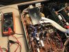
Photo attached.
Speaker output was set to off, and input was selected to Phono 2.
Can anyone offer a suggestion?
In advance, many thanks.
(By the way, the amplifier powers on and plays "ok" but this mismatch of idle current really bothers me..)

Merrylander's advice:
"Simpler than responding to individual requests here are the simple adjustments for these two receivers. I say simple because most probably do not have the equipment for an alignment. There is no DC Offset adjustment on either machine, adjusting the idle current usually reduces DC offset as a side benefit. You need a DC volmeter capable of reading millivolts, a small insulated screwdriver and preferably mini-grabber clips on the meter leads as opposed to alligator clips.
The final adjustment is done after the unit has been running for 5 or 6 minutes but I always do an initial adjustment. As to where to adjust look at the power amplifier circuit boards, the ones mounted on the big heatsinks. At the front of each board is a test point with no wire soldered to it - TP-0. Just next to it is a test point with either a brown or yellow wire soldered to it - TP-1. At the other end of the board iis a variable resistor - VR.
With power on and an unused input selected (Phono 2 is good especially if you still have the shorting plugs there) and volume set to zero put your mini-grabber clips on TP-0 and TP-1 with your meter set at millivolts. Using the insulated screwdriver adjust VR for a reading of 8 millivolts. Do this for both channels. Let the receiver play for some 5 or 6 minutes. Now, selecting the same unused input and volume at zero connect to TP-0 and TP-1 again. You will find that the reading has climbed to about 11 or 12 millivolts. Adjust VR for a reading of 10 millivolts, this is the final setting, the prior setting to 8 millivolts was simply because I knew it would rise.
A side note: Sometime tweaking VR has no effect at all, the meter will read zero and not change. About 90% of the time this is because the 2SA844 (or simply A844) transistor that sits just under VR has gone south and need to be replaced."
On a Yamaha CR-1020 I’m having trouble getting the idling current to adjust to anywhere near 10mV.
Left channel: 100.4mV
Right channel: 0 mV
Following Merrylander’s advice (see below) I’ve replaced both 2SA844 transistors that sit just under the variable resistor.
I’ve also replaced both VR’s with Bourns multi-turns.
The entire PSU and Capacitor Board has been recapped and the two 2SD234’s have been replaced with TIP31’s.
All glue on the PSU boards scraped away cleaned.
What could be the problem?
Photo attached.
Speaker output was set to off, and input was selected to Phono 2.
Can anyone offer a suggestion?
In advance, many thanks.
(By the way, the amplifier powers on and plays "ok" but this mismatch of idle current really bothers me..)
Merrylander's advice:
"Simpler than responding to individual requests here are the simple adjustments for these two receivers. I say simple because most probably do not have the equipment for an alignment. There is no DC Offset adjustment on either machine, adjusting the idle current usually reduces DC offset as a side benefit. You need a DC volmeter capable of reading millivolts, a small insulated screwdriver and preferably mini-grabber clips on the meter leads as opposed to alligator clips.
The final adjustment is done after the unit has been running for 5 or 6 minutes but I always do an initial adjustment. As to where to adjust look at the power amplifier circuit boards, the ones mounted on the big heatsinks. At the front of each board is a test point with no wire soldered to it - TP-0. Just next to it is a test point with either a brown or yellow wire soldered to it - TP-1. At the other end of the board iis a variable resistor - VR.
With power on and an unused input selected (Phono 2 is good especially if you still have the shorting plugs there) and volume set to zero put your mini-grabber clips on TP-0 and TP-1 with your meter set at millivolts. Using the insulated screwdriver adjust VR for a reading of 8 millivolts. Do this for both channels. Let the receiver play for some 5 or 6 minutes. Now, selecting the same unused input and volume at zero connect to TP-0 and TP-1 again. You will find that the reading has climbed to about 11 or 12 millivolts. Adjust VR for a reading of 10 millivolts, this is the final setting, the prior setting to 8 millivolts was simply because I knew it would rise.
A side note: Sometime tweaking VR has no effect at all, the meter will read zero and not change. About 90% of the time this is because the 2SA844 (or simply A844) transistor that sits just under VR has gone south and need to be replaced."