• Please note that Audiokarma will be offline briefly for updates early on Monday morning, September 28th.

Yamaha CR-1020 Receiver Resto

Good morning everyone. I banged in at work and here I am starring at the inoperable Yamaha CR-1020 wondering where I've went wrong. AK member Avionic and I were on the phone last night discussing the cap arrangement on the PCB which holds the main filter caps. It seems that there is another cap, 1000uF 50V that I've installed backwards. By the way, for Avionic to take the time to help me like this is a testament to his kind nature and it is much appreciated! Thanks Dave.:D

So, after I've consumed the appropriate level of hot caffeinated beverage, I will begin the task of removing the PCB that contains the relay in order to remove the other PCB which contains the cap mentioned above.

Where are you Merrylander!!

:D:D:D:D


Every time I cut/ splice these wires they get shorter to the point where it's becoming a concern.

More soon......

Jim
 
On the front of that realy board there are two points for a +25V and -25V. If you don't read 25V at either one you probably negleted to chane the two 22 ohm fusistors on the board with the big caps. A couple of 22 ohm 3 watt resistors are recomaended, and while you are at it chesk the two 10 2 watt ones for value. If they look to have ever been overheated replace them with 3 watt 10 ohms.

In fact if the FM tuning meter swings left to -50 then you have definitely lost the 25 V supplies.
 
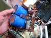
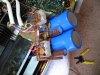
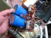
Hi Merrylander. Thanks for your interest and advice. I was just switching around the other 1000uF 50V cap. Does this pic look right to you? Have I oriented these correctly, finally?
 

Attachments

  • IMG_0591.jpg
    IMG_0591.jpg
    89.5 KB · Views: 160
  • IMG_0592.jpg
    IMG_0592.jpg
    100.1 KB · Views: 136
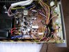
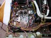
Perhaps you could look over these pictures and tell me what if anything is amiss and where are those test points to look for 25V? Are my solder/ splice wires correct?

I am ready to apply power once again to the unit to see if reversing the polarity on that other 1000uF 50V cap has done the trick. I am hesitant to keep on with this trial/ error method of tracking down my mistake. I am out of my depth, and I know it.

Live n learn.:scratch2:
 

Attachments

  • IMG_0594.jpg
    IMG_0594.jpg
    111.2 KB · Views: 136
  • IMG_0593.jpg
    IMG_0593.jpg
    108.9 KB · Views: 118
Well, I powered her up and still no good. There is no click at the relay, tuning meter still deflected to the left, but the right channel power meter is at zero and so is the left channel meter where before the right channel/ tuning strength meter was some where in the middle, oddly enough.

At a complete loss. Quite discouraged, frankly.

Should have left this one alone. It was singing sweetly and now nothing. Thought I could recap the power supply to gain longevity.

Keep trying, I guess. Thanks for any help offered.
 
Hi Merrylander. Thanks for your interest and advice. I was just switching around the other 1000uF 50V cap. Does this pic look right to you? Have I oriented these correctly, finally?

Yes, from left to right the neg should be down, to the right and then down. The reason that it is still not working is the 25 volt supplies, and that is probably why you did not blow up the caps. If you look at my photos the blue and gray resistors are likely the culprits. In your case they will be white and barn red. Sometimes the foil on the circuit side gets burned up and the six pins often need the solder re-flowed. The meter swinging left is a sure sign that the 25 volt supply is gone.

Well no photos because I can't get my subscription renewed, but right above the caps are the white and red fusistor/resisros, to the left and center.
 
I'm confused. I am sure that it wouldn't hurt to replace these two fusistors but I have never bought or replaced this type component and I wouldn't know how to proceed.

How is it that this receiver was fine in every way prior to my pulling PCB and replacing some caps, and now I need other components? Have I done something to blow those two "fusistors"- ?

Can I source them from Digikey? Happen to know what it is that I need exactly?

Are you aware of some other causes for this behavior / loss of 25V and is there a way that I could continue to trouble shoot other than R/R these two fusistors? Is fusistor the official term, or are they called something else also?

Thanks very much, Merrylander. Sorry but IDK your name??:D:D
 
Last edited:
Six pin connector and (one) fusistor check them.

attachment.php


****************************************************

You've also replaced caps on this board? Have you double checked polarity on them all? Are the voltage regulator transistors (red) solder connections stable?

Hard to tell what's going on here (yellow)

attachment.php
 

Attachments

  • IMG_0591.jpg
    IMG_0591.jpg
    90 KB · Views: 338
  • IMG_0594.jpg
    IMG_0594.jpg
    114.8 KB · Views: 335
Hello and thanks for your help. Very much appreciated. Since this piece was fine before I messed with it I am ready for a nervous breakdown!:D

The yellow areas are splices that I soldered together but haven't insulated yet since I was sure I'd be removing that PCB yet again.

I will re-flow solder joints at the six-pin, and other places you've suggested. If the six pin was not making a proper connection would I still have lights?

How do I check the fusistor since I don't have a replacement?
 
Hello and thanks for your help. Very much appreciated. Since this piece was fine before I messed with it I am ready for a nervous breakdown!:D

The yellow areas are splices that I soldered together but haven't insulated yet since I was sure I'd be removing that PCB yet again.

I will re-flow solder joints at the six-pin, and other places you've suggested. If the six pin was not making a proper connection would I still have lights?

How do I check the fusistor since I don't have a replacement?

Pull one leg of the fusistor and check the resistance value against the spec.

As Rob suggested, you don't have the 25V supplies, so that needs to be sorted out.
 
Hey people. Well I ran out of ideas for this piece and took it to a shop in my area ( Long Island, NY ) and the tech said that the CR-1020 and the CR-2020 are among the vintage components that he refuses to service. The reason: " Bit me in the ass one too many times." Said they always come in looking great cosmetically, mine is of that variety, but they are unreliable by design.

Well, I was disappointed to say the least. Now I need a new garage system to drive my Paradigm Studio 20 v2. I use a Pioneer Tuner TX-8500 ll with a roof antenna, and a Rotel RCD- 1070 for CD.

So I blew the dust off of my Adcom GFA- 5500 and the Adcom GFP- 555 ll and hooked it up to the stuff stated....

Well, nice damping factor and power into the 20's and quite nice I must say. Not giving up much with the Yammie sitting it out.


Anyone interested in a really Mint CR-1020? { Joking }

Thanks to all who tried!

Special thanks to Avionic who was beyond a doubt the nicest guy I've "met" in a long time. Thanks again, Dave.

:thmbsp:
 
Hey people. Well I ran out of ideas for this piece and took it to a shop in my area ( Long Island, NY ) and the tech said that the CR-1020 and the CR-2020 are among the vintage components that he refuses to service. The reason: " Bit me in the ass one too many times." Said they always come in looking great cosmetically, mine is of that variety, but they are unreliable by design.

:thmbsp:

That is one tech that I would avoid like the plague.:thumbsdn:
 
That is one tech that I would avoid like the plague.:thumbsdn:

+1

If I can fix a CR-1020/2020, and he can't, he's not much of a tech. :D

He should know of the service bulletin mods before making such a "unreliable by design" statement. :nono:
 
That is one tech that I would avoid like the plague.:thumbsdn:

That's interesting because he seems to feel exactly the same about my CR-1020!

Want the job? I know of your reputation that precedes you. It would be an honor to have you fix my beloved Yammie!

Lead time?
:tears:
 
+1

If I can fix a CR-1020/2020, and he can't, he's not much of a tech. :D

He should know of the service bulletin mods before making such a "unreliable by design" statement. :nono:

I would have to agree with you. I was very aggravated by his attitude and he won't see my face again.

An older couple; The "tech", and his "counter help" wife and she added, " He needs to make a living!"

Unbelievable!
 
I would have to agree with you. I was very aggravated by his attitude and he won't see my face again.
An older couple; The "tech", and his "counter help" wife and she added, " He needs to make a living!"Unbelievable!

Would you have happily paid him for the hours of labor it would have taken for him to figure out what you did? Instead of knowing what to look for in a sick CR, you gave him a mess you made yourself.

"I am usually pretty careful with this work but the reality of the situation is I don't really know what I am doing. I know how to replace caps and clean switches. When it comes to trouble I am woefully inept at tracking down the problem."

Then why were you in there? Sigh, another one dead.
 
Last edited:
Would you have happily paid him for the hours of labor it would have taken for him to figure out what you did? Instead of knowing what to look for in a sick CR, you gave him a mess you made yourself.

"I am usually pretty careful with this work but the reality of the situation is I don't really know what I am doing. I know how to replace caps and clean switches. When it comes to trouble I am woefully inept at tracking down the problem."

Then why were you in there? Sigh, another one dead.

That was sharp!

Some of this is true, and I admit it.

Since you are big on what's true, here's some for you;

If AK contained more people like you, what a wonderful place it would be.

Jim
 
Back
Top Bottom