• The move to the new server is done. There are some software and database maintenance updates in process. This has us passing the hat around to help out. We appreciate any donations. Seriously, even a dollar helps. The payment page may be found here - https://www.audiokarma.org/support.html

Yamaha CR-1020 Receiver Resto

That was sharp!

Some of this is true, and I admit it.

Since you are big on what's true, here's some for you;

If AK contained more people like you, what a wonderful place it would be.

Jim

Thanks. Did you try taking out the caps you modified and putting the originals back? You can't make it any worse at this point, I hope. Being merely a dumb Jarhead, when the parts going in don't look like the parts going out I usually stop there.

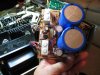
"The main caps were different then the ones I found in that the bottom pins where different. The new ones are 15000uF 80V Digikey 338-2037-ND. They had two positive, two negative, and one more. So, I snipped off one pos/ one neg, and the other one and fed them through the PCB, bent the pins over the traces/ pads and soldered them in. Pictured below. There are wires leading away from the contacts underneath the PCB and I am pretty sure I put it all back together the way that I found it."

No they didn't. From looking at the cap spec, the pins you may have used could be just mechanical supports. If so, you killed it.

http://www.cde.com/catalogs/381-383.pdf
Notes:
* Use dummy terminals for mechanical support only. Make no
electrical connection because they resistively connect through
the electrolyte to the negative terminal.
** Safety Vent may be on the bottom or on the side of the can.
 
Last edited:
I've already verified that what I've done with the main filter caps was perfectly appropriate, and is not the cause of the symptoms explained within this thread.

Sometimes exact parts are either non-existent, or beyond my reach.

Do me a favor please and get off my back!

I am here to learn and share wherever possible and if you can't get into the spirit of what this is really all about then go quote/ annoy someone else.

If you're ever drowning in NY I'd be happy to throw you a cinder block.

:D
 
I've already verified that what I've done with the main filter caps was perfectly appropriate, and is not the cause of the symptoms explained within this thread.
Sometimes exact parts are either non-existent, or beyond my reach.
Do me a favor please and get off my back!
I am here to learn and share wherever possible and if you can't get into the spirit of what this is really all about then go quote/ annoy someone else.
If you're ever drowning in NY I'd be happy to throw you a cinder block.
:D

My apologies, gear manglers are worse then Democrats. Just for giggles, assuming the caps are correct, is there anything touching the other cap terminals on the circuit board? Assume you did everything correctly, look for something simple first.
 
BTW- that link to C/D clearly states that the 50mm Dia. variety has two pos, and two neg, and one dummy....

make that two dummies!

:D

I don't see in your post where you specified the 50mm. Still worth a look at that gap between cap and board.
 
Yamaha did at one point get a bad batch of 2SD234 transistors that reacted with the silicon compound used with heatsinks, there is a service bulletin covering this. The also found that in the CR-2020 the 2SD234 was not quite up to the task of being 25 volt regulators and a service bulletin recommended replacing them with 2SD525. These are no longer available so either use a TIP41C or 2SD613. On my own CR-2020 I also replaced the heatsinks on the two with a finned one I found at Radio Shack, just remember to use the mica insulator because there are DC voltages on the metal plate of these transistors.
 
Thanks again for shedding your light on this.

:D:D

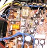
The picture below shows two transistors with brown stuff where the heat sink meets the board. I am going on DK now to find replacements.

(2) TIP41C

or

(2) 2SD613

Wish me luck!
 

Attachments

  • Transistors CR-1020 PS PCB.jpg
    Transistors CR-1020 PS PCB.jpg
    151.5 KB · Views: 123
OK. Well DK had those TIP41c Transistors and I added them to my order with four resistors, two replacement 1000uF 50V ecaps, just in case they were damaged by installing them out of phase due to faulty PCB markings. That's the last time I'll pull a cap without noting the polarity first.

"Homer" has me curious about my replacement of the main filter capacitors. Hey Merry, what do you use for those? Are there twin spade replacements that you know of? The C/D's that I used are 50mm 15000 80V and they had five pins on the bottom; 2 clearly marked pos, two clearly marked neg, and one for support.

The PCB has just two spade holes 180 out from each other and the way to use the above described replacements required that I leave just two pins, one pos, one neg, 180 out, to drop into the holes on the PCB. I bent them back over the trace and soldered them.

Have I done anything wrong and if so would I know it from some obvious result, ie- smoke, fireworks?

Is there anything that I've done that I can accept as NOT the cause of these symptoms?

Peace, Jim

:D
 

Attachments

  • IMG_0585.jpg
    IMG_0585.jpg
    86.5 KB · Views: 81
The large caps should be fine..

A Onsemi MJE15032G would probably work OK for the 2SD613 or go with the TIP's
 
Last edited:
The large caps should be fine..

A Onsemi MJE15032G would probably work OK for the 2SD613

Hey Dave!

Weekend going well I hope. You said there were some festivities planned.

What do you think of the TIP41C for the two transistors, and should I change my order to the MJE15032G ? Any advantage to this change?

Thanks, buddy.

Jim

:beerchug:
 
The Wedding isn't til 3:30PM CST.Go with the TIP's as Rob suggested.
 
Hot dogs anyone?

My "New" garage system, the successor to my sick CR-1020.

Had the GFA-5500 since new in 1997 is still going strong, real overkill for the Paradigm Studio 20 v2 but what tight bass!

SHE REALLY DOES RUN HOT THOUGH!

:yikes:
 

Attachments

  • IMG_0606.jpg
    IMG_0606.jpg
    93.3 KB · Views: 110
Six pin connector check

I've used my meter to check the two end pins ( male ) after removing the two screws that hold down the horizontal PS board, moving the board forward to disconnect that board from the vertical board it connects to, via the six pin connector.

Powered it on, grounded the black probe to the chassis, used the red probe to check the two end pins, and here's what I've measured;

Far left pin
-41.2 V That's a neg reading

same for the other side


So then what can I gather from these readings?

Sure appreciate some help here gents


Jim
 
One side should be positive and the other negative, not both negative. In any case if you have voltage there it is likely there is bad solder joints under the 2SD234s.
 
Back
Top Bottom