• The move to the new server is done. There are some software and database maintenance updates in process. This has us passing the hat around to help out. We appreciate any donations. Seriously, even a dollar helps. The payment page may be found here - https://www.audiokarma.org/support.html

Yamaha M-60 amp restoration planning

Last edited:
My solution was to use 16 gage solid wire to bridge the 2 tiny solder points on caps and use a 3” piece of 14 gage stranded wire with tips tinned with some solder to allow for easy feading into Yamaha board.
I had a thought about this, but disclaimer...I haven't tried it yet. What if a guy temporarily soldered some solder wick OR some 24 gauge wire to the 16 gauge wire in 6 inch strips. Just for fishing the 16 gauge wire through the holes. Then remove the strips. :idea:
 
I had a thought about this, but disclaimer...I haven't tried it yet. What if a guy temporarily soldered some solder wick OR some 24 gauge wire to the 16 gauge wire in 6 inch strips. Just for fishing the 16 gauge wire through the holes. Then remove the strips. :idea:
That would totally work! But with the 14 gauge wire I used with tinned tips it was really easy to fish wires thru the holes on boards. If you remove front bracket for first 2 caps and just slide thru the back 2 caps first, seat them on the board, and tighten clamp screws, then do same with front 2 caps you can easily see and position the cap leads to line up with board holes, using a screwdiver to push leads around as feeding them thru. The 14 gage wire twist provides support for cap seated on board, then just clip, fold over wire and solder to board. The only thing is if soldering with amp upside down some solder on cap posts and other wire connections may ooze down by gravity. There is a lot of tolerance to prevent solder bridges + to -, but something to be aware of.
 
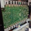
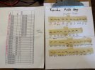
I mostly finished up my restore, replaced around 40 diodes, what a pain. The pic of lead wires is of just the 20 or so 1N4148 small signal diodes, after replacing them the clarity of the amp improved a lot!!! I left the 8 (1S1885) diodes in, they are 1A, 400-600 volt I believe. I bought 1N4004’s to replace them and may still go do that to finish up all of the diodes, unless there is any advice against wasting the time?

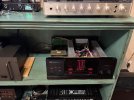
Now I need to get a good 40-50 hrs of break in on it with all new electrolytics and diodes. Any advice on how much to play it in Class A mode? I am doing some preamp swapping and comparing now for the sound. Pics for fun. It was so nice of Yamaha to face almost all diodes the same direction!!!
 

Attachments

  • IMG_1690.jpeg
    IMG_1690.jpeg
    379.5 KB · Views: 10
  • IMG_1691.jpeg
    IMG_1691.jpeg
    202.9 KB · Views: 10
  • IMG_1692.jpeg
    IMG_1692.jpeg
    324.1 KB · Views: 7
  • IMG_1694.jpeg
    IMG_1694.jpeg
    212.3 KB · Views: 7
  • IMG_1696.jpeg
    IMG_1696.jpeg
    207.9 KB · Views: 9
Glad to see we're making music vice smoke poofs...:beerchug: Looks good man.


Only diode problems I've had are the 6V Zeners you already replaced.


45 minutes at medium to high volumes. For me, the piece ran hotter at low volumes in class A. Run it hard IMO. :rockon:
You mean like hook it to the AR-9’s? Scared it will blow up. I have the DH-500 on the AR-9’s since it can hit hard dips around 2-3 ohms.
 
And as a final nod with respect to Sansui after a job well done I solder the fuse to their clamps since that area vibrates like a vintage dildo in Class A.Just kooky things I do though. Lol
The Hafler DH-500 is my second favorite amp. I fully rebuilt it with the Fantasia mods and it has a very warm and mellow sound with the mosfet outputs. Just close to 300 watts/channel. I do a lot of vintage stereo rebuilding but this is my first Yamaha.
 

Attachments

  • IMG_0707.jpeg
    IMG_0707.jpeg
    246.3 KB · Views: 7
  • IMG_0705.jpeg
    IMG_0705.jpeg
    278.4 KB · Views: 8
Back
Top Bottom