• The move to the new server is done. There are some software and database maintenance updates in process. This has us passing the hat around to help out. We appreciate any donations. Seriously, even a dollar helps. The payment page may be found here - https://www.audiokarma.org/support.html

Yamaha RX V-2095 Error Code

After the three flashes the unit doesn't power on.
Amp is in protect mode, ie self preservation to limit further damage. The unit can be put into the "Power ON inhibit"
state by removing outer case and pushing button SW85 as per service manual.

If these measured values are greater than 100mv what is that telling me?
Unexpected high voltage resulting in high current as per current=voltage/resistance. Ideally you will have about +/-25mV at each TP.
Under fault conditions you will have a few volts (not mV)

See other MA-X5000 thread for interpreting diagnostic info.
 
If these measured values are greater than 100mv what is that telling me?

I understand unexpected high voltage and high current, what would cause this condition?
 
Protection function indicates THM/OLV. You stated that the amp
was cold so OLV most likely. The service manual points to a check
of the spkr output voltage at the L&R channels (AMPPOWER boards 2,3)
So how about we follow this suggestion. Past post contains test points.

The OLV might be caused by something like a power or driver transistor
going short c-e, so you have near rails voltage (+/-65Vdc) across the
emitter resistor and spkr coil, nominal 8 ohms, nominal 8 amps...
Other causes...
 
I have made measurements at the test points as you described. Nothing measured above 50mv, most 28mv and a few at 0mv
 
The RX-V's can be complex to troubleshoot...

Protection history points to THM/OVL protection.
Problem may be in the sensor circuits causing false reporting.

THM can be checked by measuring Vdc at the test points on the CPU(1) board. Will get
alternate TP's if these are "inaccessable"
upload_2021-6-2_8-31-29.png
 
Alternate test points (CPU1 board)
CD82 pin 10 OVL TP891
CB82 pin 12 THM1 TP888
CB82 pin 13 THM2 TP889

or corresponding pins on AMPPOWER board W128B (cut wire)

For OVL, remote chance of failed sensor diode, check Vdc at D257 anode AMPPOWER board.
Repeat for D255, D258, D252, D253, D256, maybe one failed short?

upload_2021-6-2_8-48-47.png
 
The RX-V's can be complex to troubleshoot...

Protection history points to THM/OVL protection.
Problem may be in the sensor circuits causing false reporting.

THM can be checked by measuring Vdc at the test points on the CPU(1) board. Will get
alternate TP's if these are "inaccessable"
View attachment 2245333
I know I have listed this post a little off center, I actually have a MX-A5000 that I am working with.
 
I know I have listed this post a little off center, I actually have a MX-A5000 that I am working with.
When I first purchased the unit it would not start. After reading the Service Manual and Tech Support from Avionic we were able to reset the CPU and it started working fine. I also took a hair dryer to the heat sinks to see if the heat sensor would turn on and off as it should. I then put the unit into service for a few months, one day when running the unit I noticed a puff of smoke coming from the left rear and the unit shut down. I have looked as close as possible without completely pulling the unit down and don't see or smell any burnt parts.
 
Test points are for the MX-A5000.
Rather than messing around with test points, probably quicker to look for physical damage, discoloured resistor or charred
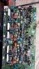
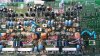
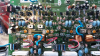
resistor, diode or transistor. Back left makes it the AMPPOWER(2) or MAIN L(3) board. Maybe post some pix, start by removing these
boards.
 
I dove much deeper into the unit this morning. I have not located any physical damage, discolored resistor, diode or transistor.

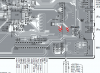
Why must I unsolder the 2SC5949 and 2SA2121 transistors shown in this diagram to perform testing them? When I connect the DCA75 to each one they all come back as "no component detected"

upload_2021-6-15_13-32-25.png
 
Amp is in protect mode, ie self preservation to limit further damage. The unit can be put into the "Power ON inhibit"
state by removing outer case and pushing button SW85 as per service manual.


Unexpected high voltage resulting in high current as per current=voltage/resistance. Ideally you will have about +/-25mV at each TP.
Under fault conditions you will have a few volts (not mV)

See other MA-X5000 thread for interpreting diagnostic info.
upload_2021-6-15_15-24-32.png
 
Why must I unsolder the 2SC5949 and 2SA2121 transistors shown in this diagram to perform testing them?

Because
When I connect the DCA75 to each one they all come back as "no component detected"

Incircuit testing can be a little tricky. The test current from the DCA75 will flow/split down the path of least resistance, not
necessarily through the item you want to test. These alternate paths can give rise to misleading results. Suggest try simple
transistor diode test, work through all 6 combinations, keep in mind low(er) resistance paths between the test points.
 
I have made measurements at the test points as you described. Nothing measured above 50mv, most 28mv and a few at 0mv

I don't see any values on this chart that are 0mv, am I looking at the wrong chart?

index.php
 
I don't see any values on this chart that are 0mv, am I looking at the wrong chart?
I'm a little confused. The chart and associated test points are for setting amps idle current and dc offset.
You've reported a (OVL/THM?) protection issue, different test points.

If you are seeing 0mV as a bias measurement then this is pointing to a problem. 0mV for dc offset would be ideal.
 
upload_2021-6-15_18-58-14.png

I have found the 5th and 6th output transistors to be shorted.

Any guesses as to cause of failure? What else do I need to check?
 
I'm a little confused. The chart and associated test points are for setting amps idle current and dc offset.
You've reported a (OVL/THM?) protection issue, different test points.

If you are seeing 0mV as a bias measurement then this is pointing to a problem. 0mV for dc offset would be ideal.
I was measuring from the test points you provided.
 
Back
Top Bottom