• The move to the new server is done. There are some software and database maintenance updates in process. This has us passing the hat around to help out. We appreciate any donations. Seriously, even a dollar helps. The payment page may be found here - https://www.audiokarma.org/support.html

Yamaha RXV transformer problem

PF Sound

AK Subscriber
Subscriber
Just got back my Yamaha RX-V3300 from a friend that used it for a preamp for a while. It quit on him a few years ago so he stowed it. When you try to power it on you get an instantaneous "click" of the relay.......on & off.......can't go to diag or anything. No display action. In the midst of troubleshooting (yes, I read all about the common cap issue with these......no joy here), I isolated it down to the power supply or the main speakers power board. Rather than soldering/unsoldering, I clipped the +/- leads from the PS to the mains (I'll use M/F spade connectors to rejoin them) & found that when powering on, the relay would click on/off like an old electronic fuel pump.......fast, slow, then stop.......PS caps charged.
Anyhow, I went back & checked the xfrmr 2ndary voltages again since they were a bit odd, & on the 5/12 leads I got nothing.......millivolts........same for the PS leads. (?) I know I have 120v going into the primaries from the standby. But when ohming out the xfrmr, I get less than 1 ohm on the primaries, & less than 1 ohm across all the 2ndaries.......like their all shorted, even the taps although the primaries/2ndaries are not shorted together.
I'm staring at this like "wtf?". All xfrmr leads disconnected.....bad readings on the leads, yet when connected/powered my DBT doesn't stay lit.

Is this what a bad transformer looks like? It's clean, doesn't smell burnt although it does look like a lot of the varnish has run off it so it has been heated.
 
Register to hide this ad
Hello

Without voltages specifications it is complicate to "rebuild" the power transfomer
You said " the varnish has run off so it has been heated " no , I don't think so , I think it is coming from "impregnation" when the transformer is manufactured
Can you post a picture of this transformer to see if there is any references on it ?
 
I've had a hard time finding any references to it via the Yammy part#.

Upon checking again, the standby is preventing AC pass to the xformer.

161.jpg 162.jpg 163.jpg
 
Not really. Since it's not testing open I didn't see the point, & I didn't want to tear into it but I guess I might as well. Finding this exact replacement is likely cost-prohibitive.
 
Unable to enter DIAG mode and immediate power off would suggest
you have an over current problem. The amp immediately shuts down
so as to protect itself.

The unit has 2 transformers, a low voltage unit that powers the CPU
that does a basic health check before enabling the main transformer.
That health check is failing due to I_Protect/Over current, note
relay below,
upload_2021-1-21_15-12-14.png
 
I kind of figured all that out, but there is 120 to the main transformer as soon as the unit is plugged in (fuse protected....there's another fuse on the standby board not shown). With all the 2ndaries disconnected, I should be able to read their outputs, yes? As soon as I plug the transformer primary in, the 120 drops to under 1v whether the unit is on or off.

OTOH, if the transformer was shorted, I would think the fuse would've blown........weird.
 
Last edited:
Thanks for responding mbz. I'm getting back to this now. I was confusing myself during troubleshooting. I isolated the xformer & applied 120vac to it......it checks out good, other than the 45vac leads only produce 40.5vac. The issue I have is that even with all the transformer leads removed from their respective boards, the standby relay won't close........ even with the primary lead removed. When I connect the primary lead & the leads for the main PS, I get that fuel pump effect I mentioned & the caps do charge but then the relay just stays open. I've left the PDD/PRY cable connected over to the processor board. I've got 4.6v going out on the PDD which is right per schematic.......about 10v on the S9 lead.....& 0v on the PRY. When I hit the "standby/on" button I get a run up to about 3.6v on the PRY lead before it clicks off. I'm assuming this is coming back from the processor board in an effort to trigger the relay.
This is where I'm unsure of things. The relay has 10vdc on both sides, then when you hit the sdby button it looks as though the PRY lead is sending dc to have Q315 drop the relay voltage on one side to trigger it..........I hear a click, voltage on one side drops for about 1 second, then another click & back to where it was. I'm starting wonder about the relay although I removed it & cleaned the contacts properly.
This is the first surround receiver I've dug into so there's a lot I just don't understand yet, like how many other "checks" the processor does before it says "OK, let's go".
 
The RX-V's are complex and sometimes a difficult repair. I've fixed a few
while there are a few in the shed that I need to have another look at.

I don't see the problem as being the main transformer, the 40.5V is probably ok.
Immediate power down points to a short, main candidates would be power and driver
transistors. You could diode test the power transistors though access is not great.
All RX-V's I've worked on don't allow access from base plate so you probably need
to remove the power PCB (with voltage regulators etc...)

The relay appears to be behaving correctly ie,10V(12V?) then drops (current through relay, click)
then fault (short) detected and relay released. Don't bother cleaning/replacing relay, problem
elsewhere.

One of the channels is faulty. Need to work out how to isolate each/some of the channels, try
diode test first, work through 6 combinations, amp powered off/unplugged. Test Q55->Q64

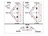
Nice graphic from markthefixer on diode testing transistors
DiodeTest.JPG

Will try and see if can isolate channels by lifting connectors, eg, CB8
 
You're right about the relay. I removed it & checked it with a 9v batt......it's good.
My first suspicion was a bad OPT, so I checked them........all good. In fact I ended up checking every transistor related to every channel amp & found no shorts. I have removed the PCB & checked every component.......all good. I checked every component on the standby (even replaced the caps on suspect) but no luck. The main filter caps & bridge diode test good.

I figured, after finding no faults on those boards, that I could isolate the problem by disconnecting all the power leads to said boards & work it forward from the standby board. That's where I'm at, & that's what led me to think the transformer might have been bad.
1. The relay on standby doesn't close when only the standby board is connected........& won't close when transformer primary connected either.
2. With standby, transformer, & only PS with main filter caps connected I get the "fuel pump effect" where the relay clicks on/off til the caps are charged then it stays open. Same thing if I add the connection to the main speaker board ( I cut/added spade connectors for easier isolation), which verifies that board isn't the issue.

There isn't much info out there regarding repairs to these type of units (other than the common cap fault on standby board) so I don't know exactly what conditions must be met before the unit will "allow" power up condition, ie allow that relay to close. There is one vid on ytube that shows briefly how the protection works, & suggest that the analog IC being bad is a possibility.
 
Try disconnecting connector CB5 near the main caps, you've probably tried something similiar.
Then attempt power on, expect a slightly longer delay before power off.
upload_2021-1-27_7-57-4.png

EDIT: Disregard, crossed communication, give me a moment to digest your latest post
 
I need to step out for the day job.
With everything connected the relay clicks at p-on (good). With only the standby board connected there is no relay click, so
this is a step backward. Suggest reconnect "everything" back to relay click then lift connector CB5 as above and p-on.
 
I need to step out for the day job.
With everything connected the relay clicks at p-on (good). With only the standby board connected there is no relay click, so
this is a step backward. Suggest reconnect "everything" back to relay click then lift connector CB5 as above and p-on.
Actually.....no. The relay closes briefly (like 1 second) then opens under all conditions OTHER than with the CB5 connected, which is when I get the clicking on/off until the caps charge, then it stays open.

Man, tracing out the these schematics is a job in itself. The big question for me is whether the standby board can/should operate on its own without any other boards powered up. I know nothing operates if the #311 plug on the standby is disconnected from the "function" board, which houses the control IC. The on/off switch for the unit won't operate with that plug disconnected.
Here's what I've discerned today. Connector #311 to the "function" board has 4 leads:
PDD- provides 4.6vdc to a "power detect/reset" portion of the board & ends up on pin 27 (PDET) of the "main-u-com" IC.
S9- provides 10vdc (supposed to be 8.8) to the same circuit, connecting to a 5vdc regulator that supplies 5v to a few points on the same IC.
MG- ground
PRY- provides what should be 1.1vdc from pin 115 (PRY....same IC) back to standby to shunt the relay voltage thus closing the relay. I'm getting 3.4vdc at the standby board for that one second that the relay closes then opens again.

So now I'm wondering if that's causing the problem........if that "over voltage" condition is constantly resetting the "power on" demand.
 
Last edited:
Think you need to take a step back and work on an overall view, eg,

p-on causes PDET to u-com, assume u-com does some basic checks and probably
RESET/RESET_ACK to surrounding IC's. If all ok then high voltage supply is
turned on (PRY), relay clicks, all ok up to this point. A fault is then
detected, possibly over current and the u-com orders the relay to be released.
So something tied to the HV supply is failing, common candidates are power
amp transistors, while these have passed diode test it's unlikely that your
tester will provide sufficient current to test the outputs so there still
may be a fault there. Think you should be looking downstream of CB5.

The relay closes briefly (like 1 second) then opens under all conditions OTHER than with the CB5 connected, which is when I get the clicking on/off until the caps charge, then it stays open.
Confirm, with CB5 not connected, relay cycles then finally stays open (or closed?). Any HV AC on the CB5 pins(male)?

The big question for me is whether the standby board can/should operate on its own without any other boards powered up
Board can't operate solo, certainly needs #311 for PDD and PRY. With CB5 disconnected maybe it can stand up solo but
more likely the u-com will detect the missing voltage and make another attempt to connect, ie, the u-com might do a RESET
the order PRY high, possibly repeat 5 (or so times), possibly being the cycling you are hearing rather than caps charging
up which would be very quick (2-3seconds?)

Will look at lifting some jumpers that supply the +/- rails to power amps
 
Confirm that the red and blue wires on the power amp are wire wrap(never undo) or plugs of some sort
upload_2021-1-28_7-46-16.png
 
My V1800 failed like that - power it on, then it would power down.

I took it to a local tech - turned out it was a faulty bridge rectifier. It's been working great for years.
 
u-com will detect missing CB5(AC) via the PRV pin. The amp sums the output
from the voltage regulators and unregulated supply and checks if within spec.
See W17(3 CMCON, pg 79), Q4, W15 VP, page 80 CB334, CB332, CB333(PRV)
 
Maybe I need to clarify something. On this unit, the standby board is it's own unit. The only thing that plugs into it is transformer primary & plug #311, & of course the leads from the 120vac plug. The filter caps/bridge rectifier are on a separate board next to it. CB5 from transformer plugs into that board, then the feeds from that board to the amp board are soldered on both ends. That's why I mentioned that I cut those leads & spade tipped em to isolate instead of unsoldering.
 
u-com will detect missing CB5(AC) via the PRV pin. The amp sums the output
from the voltage regulators and unregulated supply and checks if within spec.
See W17(3 CMCON, pg 79), Q4, W15 VP, page 80 CB334, CB332, CB333(PRV)
Thanks for that. You chimed in while I was posting, lol. Knowing that helps a lot.

I checked the Bridge rectifier a couple times & it doesn't show shorted, but I'm gonna pull it from the board & check it again.
 
Back
Top Bottom