• The move to the new server is done. There are some software and database maintenance updates in process. This has us passing the hat around to help out. We appreciate any donations. Seriously, even a dollar helps. The payment page may be found here - https://www.audiokarma.org/support.html

Yet another Heath W5M rebuild

I came across a bunch of 390 mf 450v caps. Any way I can use them in place of the can cap?

Where do you buy the big PIO caps?

Sure, you can use them, as long as they are after the choke. I would run two in series for 900VDC in the second and third nodes.

As far as the oil caps, I've been stockpiling them for a few years. I cruise fleabay and places such as Surplus Sales of Nebraska and pick them up when I see a good deal. Let me know if you need a couple and I'll send 'em out for postage.
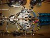
 
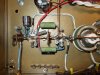
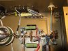
Got the rest of the bias balance circuit wired in. The two leads going to the rheostat/100k resistor connection were a booger to solder in! I had to get out the dremel tool and remove some plating before the solder would stick. The 1uF 630V Obbligato output tube coupling caps are on order. Up next, the plate supply connections and caps for the 6CG7s.
 

Attachments

  • DSCF7203.jpg
    DSCF7203.jpg
    112.7 KB · Views: 124
  • DSCF7204.jpg
    DSCF7204.jpg
    109.1 KB · Views: 109
47K 5W plate load resistors for the 6CG7 driver installed and just about finished with being wired up to their own filter node per triode section. Also installed are the 47uF and 100uF filter caps for the 6CG7 input voltage amp and phase splitter.
 

Attachments

  • DSCF7205.jpg
    DSCF7205.jpg
    130.4 KB · Views: 103
  • DSCF7206.jpg
    DSCF7206.jpg
    113.8 KB · Views: 97
Man, I'm glad I found this thread.

OP, you do very nice work. I've been building and repairing Amateur Radios and HiFi gear for 30 plus years, and I'd rather send my stuff to you. Very fine work indeed.

That happens to be one of the Rigs I wish I had built back in the day. I built many Heathkits, but no audio gear. Just Amateur Radios and testing equipment.

Love the pics. Nice project. You should be proud of your work. It's magnificent.
 
"Quality is never an accident; it is always the result of high intention, sincere effort, intelligent direction and skillful execution; it represents the wise choice of many alternatives"
 
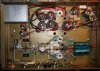
NFB loop wired in. Note the change in value of the 4.7K feedback resistor to 10K. This is because of the changed bias points in the front end and phase splitter.
 

Attachments

  • DSCF7207.jpg
    DSCF7207.jpg
    114 KB · Views: 183
Here's where we're at now. Just need to finish wiring in the plate supplies for the front end and phase splitter and then the AC line. I may also wire up a couple of test points on the now unused preamp connector.

And, of course, I'm waiting for the output coupling caps. I'm also going to use Teflon bypasses on the output tube cathode caps.
 

Attachments

  • DSCF7210.jpg
    DSCF7210.jpg
    132.9 KB · Views: 186
  • DSCF7211.jpg
    DSCF7211.jpg
    110 KB · Views: 158
Last edited:
An extremely clean build. Wow. Although I don't think those wire wound pots are quite big enough. Jeepers, where did you source those monsters?
 
An extremely clean build. Wow. Although I don't think those wire wound pots are quite big enough. Jeepers, where did you source those monsters?

Yeah, I know.....I'll work on that.

I got them off of Ebay. I was looking for 10 watt rheo's and the closest I could find were these 25 watters. Shouldn't be a problem with current flow causing any pitting at the contact point!
 
Blast it all, I can't find the 3.9K and 47K 5W wire-wound resistors I ordered so I had to order some more. Of course, I'll find them right after the replacements come in.
 
Got the output tube coupling capacitor networks in place. These were kind of a booger to put in. Won't be long now!
 

Attachments

  • DSCF7316.jpg
    DSCF7316.jpg
    109.9 KB · Views: 174
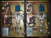
Here's the pair at about 95% or so completed. Just a couple of components for the front end and then wire up AC power, a switch and fuse, and a surgistor. My arm/shoulder is telling me it's quitting time.
 

Attachments

  • DSCF7319.jpg
    DSCF7319.jpg
    139.1 KB · Views: 156
How much of a difference sonics-wise have you noticed using bypass caps on the output couplers?
Should the bypass caps be 1/10th the value?
 
The best way I can describe it is increased smoothness AND resolution. For this type of use, I haven't found the 1/10th "rule" to really apply. And that's a good thing in this case because it would be just about impossible to fit a pair of .1uF teflons with a high enough voltage rating.
 
Jim,

I've thought about installing some bypass caps on the output couplers too.:yes:
I have some of the .1uF T3 Russian teflons but, like you say, there's not much available space. The Obligatos 1.0uF are space hogs. Would Russian K40y-9 1000deg. oils do any good? I also have some Russian teflon T1 0.015uF's but they're only rated to 200 deg.

..Roy
 
I've got my chassis painted as well as my transformers. Time to order parts. Did you ever get a list made. How about a schematic?

I'm going to use some 6L6s I already have for output tubes. Will any changes have to be made? They are older Wing C tubes.
 
Hey Guys,

Sorry I've been away for a bit. Today is day 11 in a row for work. I'm currently at the Umatilla Army Chemical Depot in Oregon, supporting an exercise for the National Guard. A few more days and I should be home....Thank God!

I'll get the W5Ms finished when I get back and then the final schematic and parts list. If I have time I'll shoot some video of them running and link it.

Br1ck, your 6L6s should run just fine, but keep an eye on the plate current and balance for a bit when you first bring your amps up.

Ugh, back at it.
 
Back
Top Bottom