• The move to the new server is done. There are some software and database maintenance updates in process. This has us passing the hat around to help out. We appreciate any donations. Seriously, even a dollar helps. The payment page may be found here - https://www.audiokarma.org/support.html

Yet another Heath W5M rebuild

My setup is still pretty much the same with the AVA T7 pre, Heathkits and Omega single driver bipoles as the core.

However..... I'm about to embark on a speaker build using SEOS 18 waveguides, BA750 compression drivers and Acoustic Elegance TD15M mid woofers to go along with my 3 subs. I'll probably add a Rythmic sub to the mix in the future.
P1080116.JPG

P1080082.JPG

Dang! We have got to get together and spin some tunes!
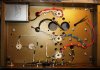
 
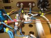
Heater wiring installed (except for the center-tap) and I bought some blue heatshrink and re-did the output transformer primary side leads. All of the heater wiring is silver-plated stranded Teflon. If you look at the 9-pin sockets, you'll see that the heater wires go to pins 4 & 5. That's so the amps can use 6CG7s instead of 12AU7s.
 

Attachments

  • DSCF7131.jpg
    DSCF7131.jpg
    92.3 KB · Views: 195
Learning here.
So, I know you don't need the silkscreen ID'ing the tubes and stuff, but will you put something on if these'll get passed along? If so, how?
 
I'll include a copy of the modified schematic for the owner. If he wants to put dome dry transfer labels by the tube sockets, that would work.
 
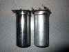
Got the original old can caps polished up and installed. Hey! These are starting to look like real amplifiers!

The can caps will only be for original appearance, they will not be in the circuit.

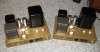
Now the fun starts: Let's start wiring these babies up!
 

Attachments

  • DSCF7133.jpg
    DSCF7133.jpg
    144.3 KB · Views: 141
  • DSCF7136.jpg
    DSCF7136.jpg
    85.8 KB · Views: 178
Nice! I can see why these amps are sought after. I'd love to hear a pair sometime. I MUST get out more! lol
 
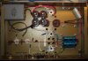
Got the first filter and second cap filter sections and choke in. You can see the 4 capacitors in the 2nd filter section, which make up a 220uF 900V filter node. This is where the center tap of the output transformer will be wired for B+. Also shown is the 110 ohm dropping resistor which will feed another filter node. The filament wiring is also in.
 

Attachments

  • DSCF7149.jpg
    DSCF7149.jpg
    98.8 KB · Views: 203
Jim, what is the purpose of those smaller film caps that straddle the pins on the electrolytics? What is their make make and size??
 
I thought I would get a little solder slung this morning before turkey and Master of Ceremony duties called me away.

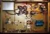
Here you can see the new main solid copper ground bus, new 350 ohm 10 watt bias resistor, standoffs, and the B+ capacitor filter bank wired to the output transformer centertap. Drawing on a 1961 article written by Talbot Blake detailing the shortcomings and fixes for the typical Williamson amplifier, the 680uF 80V output tube cathode bypass capacitors will give a theoretical cutoff of around 3hz and excellent transient response (with the new stiffened power supply) down to around 30Hz.
 

Attachments

  • DSCF7151.jpg
    DSCF7151.jpg
    90.1 KB · Views: 189
It's just about BACON smothered bird eating time, so I will likely be in a carbohydrate induced coma in a short while.

Ground bus connections to the first and second filter caps made. All transformer center-taps grounded. Next up will likely be the front end and driver wiring. I'm waiting for some new 300 ohm rheostats...and hoping they will fit!
 

Attachments

  • DSCF7156.jpg
    DSCF7156.jpg
    104.7 KB · Views: 156
Industrial RTV. The stuff holds like crazy and works well since the owner did not want any holes drilled in the chassis.
 
More progress made on the input, driver and power supply sections.

Edit: I should have added make sure you check the original cathode resistor on the driver tube socket. Some early versions of the W5M had 560 ohm resistors here, which resulted in a poor bias point. You want a 2.2K 2 watt resistor here.
 

Attachments

  • DSCF7171.jpg
    DSCF7171.jpg
    110.6 KB · Views: 197
  • DSCF7170.jpg
    DSCF7170.jpg
    116.4 KB · Views: 157
  • DSCF7169.jpg
    DSCF7169.jpg
    130.4 KB · Views: 171
  • DSCF7163.jpg
    DSCF7163.jpg
    113.7 KB · Views: 184
Last edited:
Got half of the cathode bias network wired in and the output tube current monitoring/balancing test points. This is probably the hardest part of the entire rebuild. The two 30 ohm current sampling resistors are hand matched to about 1/10th of 1%.
 

Attachments

  • DSCF7172.jpg
    DSCF7172.jpg
    126.6 KB · Views: 164
  • DSCF7173.jpg
    DSCF7173.jpg
    108.4 KB · Views: 159
Back
Top Bottom