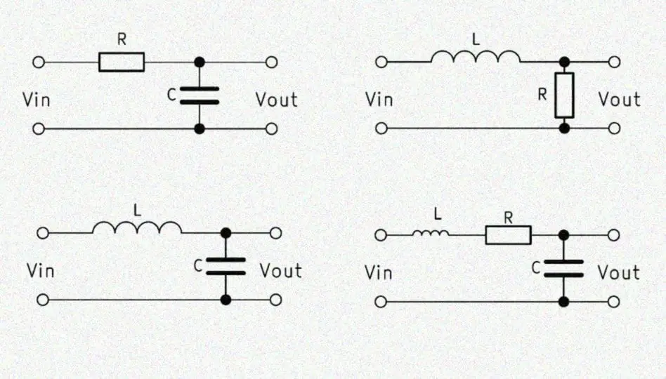
L3 and C5 form a second order low pass filter which is a kind of sharp way to roll off the top end.
LP2 is wired to add resistance to the C5 path and short L3 to take the filter out when you turn it up.
If you scroll way down on this page to LC filter calculator and enter .3mH and 5uF you'll see that
the cutoff frequency is 4.11 KHz:
1st order and 2nd order low pass filter ✓ Low pass filter calculator ✓ Low pass filter circuit ✓ Cutoff frequency low pass filter Calculator ✓ RC vs RL vs LC low pass filter ✓

electronicbase.net
When you use LP2 to add some resistance you'll soften the rate of cutoff, by lowering the Q, and take
it closer to first order and then to removed from the circuit by shorting L3 and opening C5.
You can use that calculator to see how C5 alters the cutoff frequency.
It is square law or inverse, so to double Fc you have to divide C5 by 4 or 1.25 uF with a resulting cutoff
of 8.22 KHz. If you take it too high it will have very little effect. I'm not sure how useful the control is anyway.
Usually you want a more gentle slope or even more of a shelved response which is what you'd get with it
connected as a normal L-pad.