• Please note that Audiokarma will be offline briefly for updates early on Monday morning, September 28th.

Z19 Crossover

Do you have any way of measuring the frequency response? What is the gear in the rack? Nice looking system.

BillWojo
 
No direct measurements, just my ears based on the geometry of my listening space and digitized response curves from various places around the net and modelling. I've been thinking about investing in a mic setup though.

My previously built z-19s do sound very good, but I've been curious about various capacitors and resistors for awhile, and also curious about the effects of 'better' inductors. Have seen some of the things that Jeff (from Jeff's Place) has tried with his Altec setup and I've been curious. Granted, I'm a skeptic by nature, but if I can wring more performance, or marginally better sound out of my speakers, that's a win. I, for example, am pretty skeptical of the massive improvements some people have noticed between a good cap and a ludicrous cap in various audio applications. But I wanted to see if I can detect any differences with these paper in oil motor run caps, so I'm going to live with them for awhile and see.

I can definitely hear a difference in the one side that has the prototype already. Initially, I was disappointed and extremely underwhelmed, but apparently the caps needed some time to do something, because the sound coming from that right side has markedly improved over the past 2 weeks or so. Initially, gain was lower on that right side as well - I used new Mills MRA-12 resistors instead of the sand-casters, and my multimeter seems to be on the fritz, so I ordered myself a new one for my birthday and just waiting for it to get here so I can check the resistances with my new, higher accuracy meter. Other than the very slight gain (woops, attenuation - I suppose would be better here) difference, with the new crossover I get a lot more apparent change with the lpads (I re-used the same l-pads) than I did with the old crossovers (this really confuses me a bit). It's all wired exactly the same - strange. The other thing that is in-my-face better is the background - that right channel is much quieter, and I mean several decibels. I suppose that could be a lot of things - the proximity of the coils to each other in the old layout maybe. But it's not subtle. Just that right there is worth it.

But, I'm always wanting more. So I made up as exact a copy of a Duelund graphite-core fancy-schmancy resistor as I could, but without the silver wires - I used solid core 18g tinned wire. I bought some pencil leads from my local craft store, and tested the resistances (as best I could with my on-the-fritz meter) using a 0.1% resistor for a resistance target). The 2H was much too high - was getting resistance in the 20s. The 2B gave values around 10ohms, but I was aiming for 3ohms, so the magic number turned out to be the 4B leads. These are the 2mm graphite refills for drafting lead holders. Burnt off all the coating, coiled some wire around 2mm rod, slipped it on and soldered it at one end, then slipped the other end on and moved it until I got the exact same value as my 0.1% Mills. I very carefully put this resistor into the circuit in the last resistor in series with the tweeter not expecting to hear anything.

I was mistaken. I'm not sure why, I'm not sure how, nor am I sure how to describe the difference, but there is absolutely positively something there. And I'm a skeptic. Now, I've got like 4 bucks into this resistor, so I don't have what I've previously thought of as 'investment-manifested audio placebo syndrome' (IMAPS). I'll try to make some notes as I listen more - this was just two days ago now, so don't really have a lot of time with this. I kind of did this to prove to myself that the audio Kool-Aid was just that - not so sure what to think now.

Other changes to my original parts are 14Ga inductors for the 0.33 and 0.7mH and 10ga for the 2.77. All of the caps are Ronken P61 series paper in oil and where I could not find the needed values, I paralleled a 1uF Russian K40Y9 to get the right value.

As for components, they are in my signature - don't think anything has changed. Luxman 444 with a self-retipped (I have a thread on that somewhere in here) Supex SD900 super that I rotate with a Grace F-9 and a self-repaired and tipped Lyra Helikon. That goes through a Luxman 8020 step up transformer and out to the ARC Sp-3A and then on to the ludicrously heavy Citation II (factory-built!) then to the DIY Altecs (416-8a, 806-8a / 811 horn; thread somewhere on here or diyaudio). Been quite happy with the speakers, but still need to finish them off - proper stands, grilles, and so this crossover revision is part of that finishing I suppose. I think eventually I'll end up with 802 GPA drivers at some point, and if I can ever find them, a pair of the larger multicell horns! Man those things are works of art.
 
Has anyone tried Zilch's N3134 on any other JBL Waveguide other than the 2344.

I'm thinking on building a modern version of the 4430 with M2 waveguide, 2450-SL and 2216ND. The 2216nd will be full active in this case.

Thanks,
Scott
 
Last edited:
I built one crossover ( loosely) for testing purposes... I'm finding in my speaker which is a 19 clone but I'm using a JBL 2231 woofer and a BnC compression driver (250d) 8ohm.
The bottom end sounds great but I seem a bit rolled off on top, I'm guessing that's due to my 8 ohm tweeter?? Anyway, I copied Zonkers diagram , which values would I tweak to up the high end? Looks to drop at around 8000 Hz.
 
I built one crossover ( loosely) for testing purposes... I'm finding in my speaker which is a 19 clone but I'm using a JBL 2231 woofer and a BnC compression driver (250d) 8ohm.
The bottom end sounds great but I seem a bit rolled off on top, I'm guessing that's due to my 8 ohm tweeter?? Anyway, I copied Zonkers diagram , which values would I tweak to up the high end? Looks to drop at around 8000 Hz.

The Z19 was prototyped with the 8ohm B&C 250 driver on a 511a horn ( therefore your "guess" about the 8 ohm impedance of the driver being a problem is right out the window ).

You shouldn't really have any HF problems with a bonafide B&C 250 on that big radial horn you're using ( assuming your B&C driver is healthy ).
- You are using real B&C de250's right ??

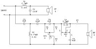
You might want to double-check your Z19 parts-wiring ( for a mis-wire in the LP2 section ).

L3 + C5 ( along with LP2 ) create a HF roll-off ( the roll-off occurs when LP2 is not cranked wide-open ).
- I'm thinking that a backwards wired LPad ( LP2 ) might display the symptoms that your describing.

index.php


You can reduce resistor R7 from 3R down to as little as "not present + totally shorted" to get more overall horn-driver level.

:)
 
Last edited:
The Z19 was prototyped with the 8ohm B&C 250 driver on a 511a horn ( therefore your "guess" about the 8 ohm impedance of the driver being a problem is right out the window ).

You shouldn't really have any HF problems with a bonafide B&C 250 on that big radial horn you're using ( assuming your B&C driver is healthy ).
- You are using real B&C de250's right ??

You might want to double-check your Z19 parts-wiring ( for a mis-wire in the LP2 section ).

L3 + C5 ( along with LP2 ) create a HF roll-off ( the roll-off occurs when LP2 is not cranked wide-open ).
- I'm thinking that a backwards wired LPad ( LP2 ) might display the symptoms that your describing.

index.php


You can reduce resistor R7 from 3R down to as little as "not present + totally shorted" to get more overall horn-driver level.

:)
I'll look over my mess. Thanks! Yes the drivers are real B and C. What's the thought on break in time here?? I've got maybe 10 to 15 minutes only
I would have thought the crossover was designed for a Altec 801/901 driver?
 
Last edited:
I'll look over my mess. Thanks! Yes the drivers are real B and C. What's the thought on break in time here?? I've got maybe 10 to 15 minutes only
I would have thought the crossover was designed for a Altec 801/901 driver?

Break-in for HF diaphragms "might" effect the lower frequencies if the suspension were to actually loosen up some.

This hasn't been documented as happening.

HF won't magically appear due to a looser suspension.

The Z19 is an Altec network design ( though obscure ) that was used with the Altec 604-8H duplex ( the workings of this network were first committed to paper by Jeff Markwart and Jim Easley (??) and published in Jeffs Markwart corner website > which is now gone ).

:)
 
Break-in for HF diaphragms "might" effect the lower frequencies if the suspension were to actually loosen up some.

This hasn't been documented as happening.

HF won't magically appear due to a looser suspension.

The Z19 is an Altec network design ( though obscure ) that was used with the Altec 604-8H duplex ( the workings of this network were first committed to paper by Jeff Markwart and Jim Easley (??) and published in Jeffs Markwart corner website > which is now gone ).

:)
I thought Jeff Markwart crossovers were crossed higher?? 1600hz or so?
Isn't the Z19 crossing at 1000hz?
 
Coming back to this thread... Things have changed a bit, I can't recall why I was having hf rolloff as I had stated , but I did remake the xovers to a more compact size so they would be able to fit inside my horn enclosure. After sorting that all out, I'm finding too much hf output, a bit too hot for my liking ( or room?) would increasing R7 reduce the horns output? TIA
 
Last edited:
You have 2 or 3 pretty simple options.

#1) Increase the value of R7 by an extra 1 to 4 ohms ( that'll decrease the overall horn level ).

#2) Roll-off more HF//UHF ( using LP2 as it's currently wired up ) as well as pull down the midrange on the horn by adjusting LP1 ( which is setup to suckout the midrange ).
- Balance to taste.

#3) Remove L3 and C5 from the circuit and then reconnect LP2 to act as an over all level control for the horn circuit ( rather than acting as an HF//UHF roll-off control ).

:)
 
Last edited:
You have 2 or 3 pretty simple options.

#1) Increase the value of R7 by an extra 1 to 4 ohms ( that'll decrease the overall horn level ).

#2) Roll of more HF//UHF ( using LP2 as it's currently wired up ) as well as pull down the midrange on the horn by adjusting LP1 ( which is setup to suckout the midrange ).
- Balance to taste.

#3) Remove L3 and C5 from the circuit and then reconnect LP2 to act as an over all level control for the horn circuit ( rather than acting as an HF//UHF roll-off control ).

:)
Thanks! I've done #2 and can't quite get a balance that satisfies...
I will try option 1 and if no go then option 3!
I just noticed I had written R3? Changed that to R7...
 
Last edited:
Back
Top Bottom