• The move to the new server is done. There are some software and database maintenance updates in process. This has us passing the hat around to help out. We appreciate any donations. Seriously, even a dollar helps. The payment page may be found here - https://www.audiokarma.org/support.html

Z19 Crossover

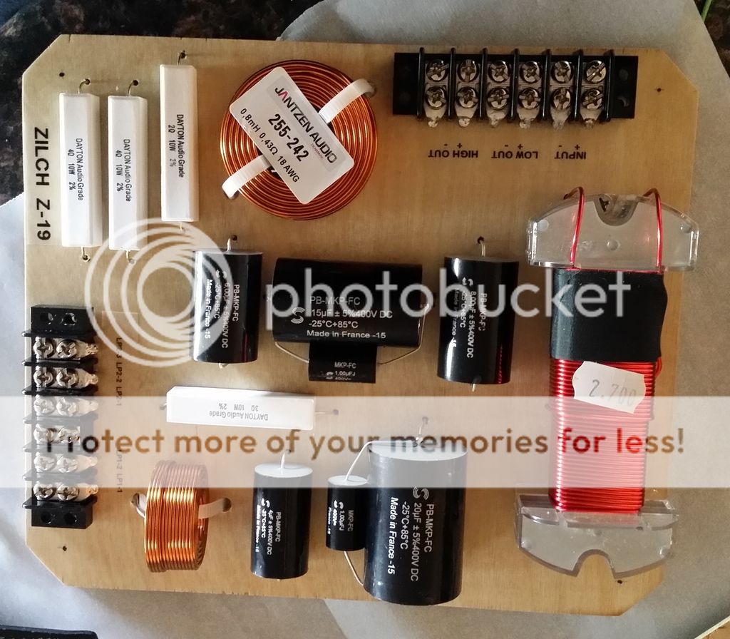
Okay, so in the interest of keeping all Z-19 stuff together, I'll revive this behemoth instead of starting my own thread. I've built a great pair of speakers with a pair of 416 8a's, a pair of 806's on 811b horns. I used some off the shelf Eminence crossovers and I've sourced the parts and laid out my crossovers. I have not used my schematics 'skills' in a few years and I would just like a confirmation that my wiring diagram follows the original circuit. I've made the circuit a single input, so mine is not biampable. Aside from that difference, can someone please confirm? I've gone through it twice, and can't find anything amiss... Thanks in advance!

JOE_Z-19.jpg


attachment.php


And one of my layout...
20160123_234128.jpg
 
You have the woofer circuit incorrect- after passing through the 2.7 inductor the signal does not pass through the 21uF cap- but intercepts it then passes through to the woofer.
DC
 
Here's the one I pasted above; I think it's right. I didn't go through the whole thing, but I think yours correctly connects joins L1's output and C1's input to the woofer's positive input.

index.php

JOE_Z-19.jpg
 
Last edited:
Now I see it, you are connecting to the woofer at the top of the drawing- my mistake then. sorry.
DC
 
In my drawing, I'm connecting to the woofer at the bottom - I only have the single input - no plans on ever biamping - two deuces would break the bank. And the furniture. Thanks guys. I start soldering tonight!
 
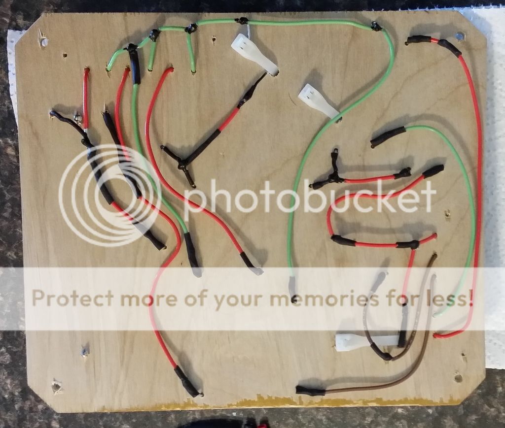
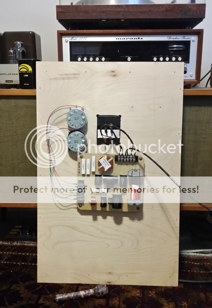
Just to update. Both crossovers finished and installed. They sound amazing! This is the first time that a change I've made in my audio system has smacked me in the face! They are really as good as the hype - fantastic. Now I just need to get the levels set properly! Here are a few more photos of my layout, and the back for an idea on the wire routing.

20160130_150320.jpg

front

20160131_153918.jpg

rear showing wire routing

20160131_163103.jpg

installed on the back panel of the speaker.

Fun project. I took my time - figure I have about 20 hours into it. I was thinking of doing this as an external, but I'd want a more exotic species of ply and I think I'd use turrets if I did that. The board is mounted on some 1/2" nylon spacers from home dumpster.
 
Woah, it's been ages since I've seen that! I built the HF portion into the box with my JBL 2345's with 2425's. I wish I had got those little square L-Pad mounts that PE had with the Mid and High labels to make it easier to remember which was the variable resistor (Mid) and which one was the L-pad (High).

If I had it to do again, I'd put the L-pad with it's 3 wires on top so it was easier to remember it was the highs. As it is, mine are side by side. The variable resistor is a 50 Watt jobbie, so it is pretty easy to tell them apart by feel...
 
Very nice work! I have built dozens of these and your's certainly rivals my best!!
DC
 
Thanks guys. Really had fun building them. Lots of good info in this thread. They are on a pair of 145 l. internal volume boxes that I built up over winter break. The boxes are put together like this, with a couple more pieces of internal bracing. 3/4" birch sides, 1.5" baltic birch front baffle, 3/4" top and bottom, 3/4" back. Two 3" ports 8 inches long, cabinet tuned to ~30Hz - not sure exactly because I gather using open weave damping material increases effective volume? The drivers are Heathkit Altec - a pair of 806a's on 811b horns and a pair of 416 8a's - although I have been told that these have the same TS parameters as 803B's. Modelling the box in WinISD gives slightly better results on the low end using 803B parameters (but with a very gradual LF rolloff). Win ISD has no 416 8a parameters, so I was using TS params I found listed online (here somewhere I believe). Don't have any great photos of the boxes, but here are a couple. They will be finished in some ***AMAZING*** red gum veneer flitches that I've picked up, but that won't be until summer break. I plan on doing a curved 3/4" horn cradle that will be veneered with the same wood as well.

I am really enjoying these. Listened to some vocal stuff this evening. Everything I throw at these they seem to enjoy. Tonight it was The XX's self titled LP and some Johnny Cash. Wow...

b9ea8f07-a492-4bb0-ac69-b67d44aacac5.jpg

render

20151231_162734.jpg

during the final stage of box construction

Plan for holding the horn.
horn.png


Some things that I still need to do - damp the horn a bit. I'm going to do this with modelling clay I think behind the lip so it can't be seen. Truthfully, I don't think I have heard the ringing that some folks talk about, but I don't really play music at super high volumes. I don't need to turn the volume up very much at all with these to get quite some decibels. With my deuce driving these, I'm generally a bit above 1/4 volume. Loving these speakers.
 
Ooh, I bet that sounds great. I love the bent stand for the horn; you totally need to do that.

I'm wondering now whether the ringing that I (very rarely) experienced with my Valencias wasn't caused by the woofer's back waves. (Bowtie insists that the horn driver doesn't produce enough energy to cause it.) If that's the case, then you wouldn't need to worry about that with your design.
 
Last edited:
So has anyone made the circuit boards available to purchase? I have a set of HeathKit AS101 speakers (Altec Valencias) that I'd like to try this with.
Thanks

BillWojo
 
Anyone still making these, I just scored a pair of 19s and would like to carry on a Zilch legacy.
 
I have built several of these networks, I reuse the original inductors on the the original Altec plates.
DC
 
I looked for awhile and gave up. I'm in the process of building a set of Altec Model 19 crossovers and I'm just going to mount it all on a piece of wood. I'm using mostly vintage oil filled capacitors anyway so the PCB would not be of much help as they are large metal cans.
I think if someone made some nice heavy high quality PCB's that there would be a small steady market for them as folks discover the magic of Altecs and want to do upgrades.

BillWojo
 
There were a couple of guy here that made some Z19 PCB's but do not know if they are still to be found here again! I have made several Z19's on wood blocks as well! Zilch designed the Z1 crossover along with a parts list...........It might have been in the econowave thread. Let me know if I can help you
DC
DC
 
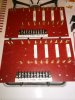
CAM01378.jpg CAM01378.jpg CAM01381.jpg Started working on my crossovers finally. Decided to use 1/8 thick fiberglass electrical board and brass screws to make it like a turret board. Caps will go on last so they can easily be pulled off and other types substituted in. I have a pile of vintage oil caps to try out.
The square boards in the background are the same material and will fit into the backs of the HeathKit AS101's when I remove the stock crossovers. Last time I was in there I carefully measured the mounting holes. These will just screw in place and the crossovers will hook up externally so I can play with caps

BillWojo
 
Last edited:
CAM01379.jpg
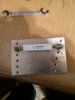
This is a little fixture I made up to solder on the ring lugs to components. This way they just drop down on the threaded screws. The photos are crappy cell phone pics but all the hole locations on both the fiberglass and aluminum fixture were carefully drilled on a Bridgeport for accurate location.

BillWojo
 
Last edited:
Back
Top Bottom