• The move to the new server is done. There are some software and database maintenance updates in process. This has us passing the hat around to help out. We appreciate any donations. Seriously, even a dollar helps. The payment page may be found here - https://www.audiokarma.org/support.html

Zenith console help!

Forsythe93

New Member
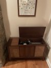
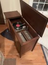
Hi everyone! First time poster. I’ve got a bit of a project on my hands. I picked up a Zenith RN2601 console from Facebook marketplace and of course, it has problems. The left channel is out, the audio is extremely quiet(about the volume of an iPhone), and it has virtually no bass. FM, AM, and Phono all function equally but with that issue.

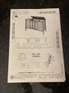
I bought a service manual off eBay, ripped off the back, pulled out the amp, and started replacing dead caps. I’m completely shooting in the dark. I want this to be a bit of a learning experience and soldering practice but I would also like to avoid replacing every component on this unit haha.

I have also isolated the turn table and speakers on another amp and they sound great.

Where should I look guys? Vacuum tubes, resistors, more caps?? Thanks for any help!
 

Attachments

  • IMG_0120.jpeg
    IMG_0120.jpeg
    113.9 KB · Views: 53
  • IMG_0119.jpeg
    IMG_0119.jpeg
    105.9 KB · Views: 56
  • IMG_0118.jpeg
    IMG_0118.jpeg
    98.4 KB · Views: 57
  • IMG_0091.jpeg
    IMG_0091.jpeg
    102 KB · Views: 56
Register to hide this ad
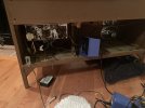
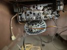
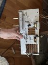
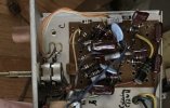
Pulled it back out and took some more pictures for clarification. What I understand to be the tuner has 6 tubes but the amp doesn’t have any. So I take it my amp is solid state? Therefore am I even posting in the right spot?

Needless to say the caps I replaced had no effect on audio or function.
 

Attachments

  • IMG_0121.jpeg
    IMG_0121.jpeg
    119.4 KB · Views: 37
  • IMG_0122.jpeg
    IMG_0122.jpeg
    130.1 KB · Views: 39
  • IMG_0123.jpeg
    IMG_0123.jpeg
    100.7 KB · Views: 37
Get a can of De-Oxit and clean all the pots and switches

It is possible that the amp and tuner share some power via an umbilical and they have to be connected for anything to work.
 
Last edited:
Yes, from the pics and documents that's a transistor amp/preamp with a tube tuner. So, it's your choice of SS or Tubes forum depending on what issues you need help with.

You say that the issues are the same with either tuner input or phono input, which might imply that the main signal loss problems are in the SS amp chassis. So, that would be where I would focus. If you're lucky, it could be switches, pots and any connectors so give them a clean out to see if that changes anything. Otherwise, you could start checking voltages and values vs. schematic to find inconsistencies.

If you would prefer this in SS forum for troubleshooting help there on the amp, this thread can be moved.
 
Thanks all for the replies I’ll grab some deoxit and go to town. I went through some of the resistors and their reads were good but there are a ton more that could be toast.

After looking at the tube descriptions all are am/fm related but one limiter and one discriminator

That would be great if you could flip this thread to the SS forum.

Thanks again all!
 
These amps use electrolytic caps in the preamp signal chain. I think the brand is El Cheapo or should be. These caps have a shorter lifespan than the ceramics you have and the brown film caps, which you can leave alone.

Look at the two gray caps in the top of your three boards. If the value on that cap is anything over 1uF then it is an ecap and needs to be replaced. Thats what I would do next.

Have you posted the schematic?
 
Thanks for the reply RWood. Good to know about the ceramics and brown ones.
The two grey caps? Not sure which ones you mean. The pictures where I’m holding the unit is the front and back side of the amp. The one still mounted in the console is the tuner as I understand it.

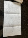
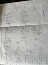
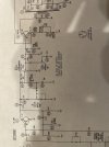
Attached is the schematicIMG_0129.jpeg
 
It’s this board where I see three suspect caps. They are white or light gray. What are the values of those?


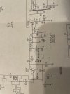
The schematic is too blurry the see part numbers, but you can see the first coupling cap coming off the transistor after the selector switch. Maybe C11, it’s hard to say. The signal needs to be able to pass through these caps and those in the next stage.
 

Attachments

  • IMG_4390.jpeg
    IMG_4390.jpeg
    47 KB · Views: 20
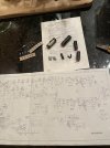
Ok I tested them c36 c37 and c41 c42. All were Supposed to read 5uf but instead readings were 4nf/8nf and 132nf/21uf respectively. I’ll go ahead and swap them.image.jpgimage.jpg
 
Those pics are much better. There’s a pair of 100uF caps you should change: C38A and B. Seems like they might be together in one tube, but the new ones can be separate.

And I suspect there are output caps coming from the power amp. If you can show a better picture of what happens to the right of where we’ve been looking I can give you the part #s.
 
Last edited:
Awesome I ordered all of them a couple days ago from mouser based on the part#s on the back of the Spec sheet. Should get here by this weekend, I’ll report back then!
 
Well…13 new caps in there and this thing sounds awesome!!! Thanks @RWood for all the help!
 

Attachments

  • IMG_0149.jpeg
    IMG_0149.jpeg
    76.1 KB · Views: 12
  • IMG_0150.jpeg
    IMG_0150.jpeg
    127.2 KB · Views: 12
Glad to hear it! Thanks for reporting back.

That’s a nice looking console and it fits very well in that space.

Rock on!
 
Back
Top Bottom