My Low Noise PSU

HypnoToad

Ms Puss Puss
Subscriber
I wanted to try a Low Noise PSU to use with low current draw devices like phono preamps.

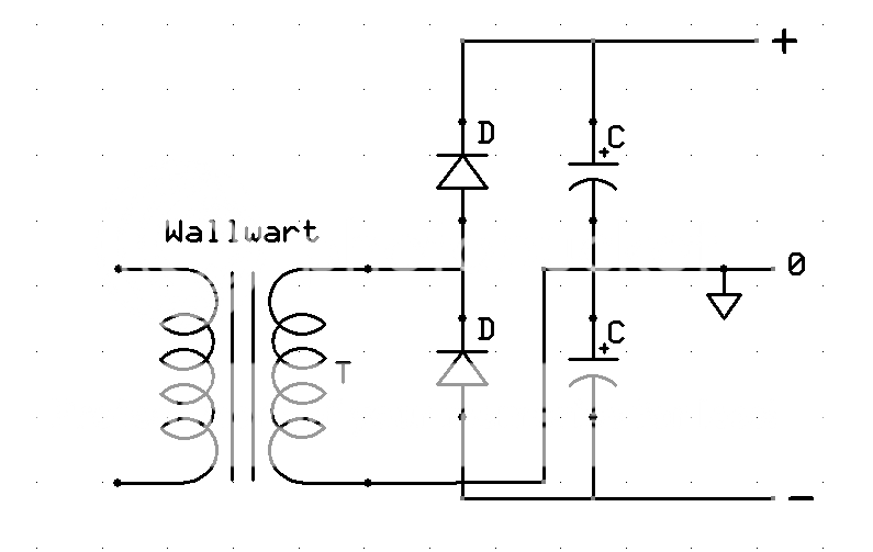
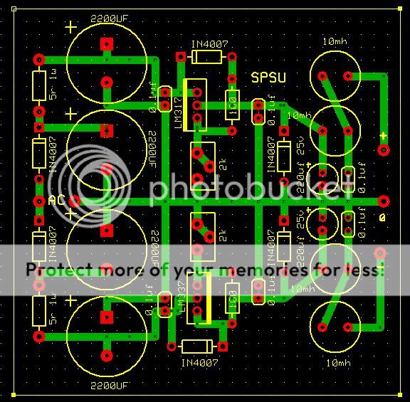
I designed this one with trimmers and chokes, I have it running off a 12v AC 1 amp wallwart as I have a thing about messing with mains power.

It runs my phono preamp just fine and to my surprise has as little noise and sounds as good as my SLA batteries.

It can be adjusted up to + & - 15vdc, I have it set at 13vdc. The PCB is only 2.5" x 3.5".

PSU1_zps19121d78.jpg


Back with switch and socket for wallwart.

PSU2_zps7e4ab580.jpg


Front with LED.

PSU3_zps094209ef.jpg
 
Nice work!

I haven't been following your other threads, and I don't recognize the brass colored inserts at the component holes. Is that something that you can press into the PCB from the bottom? Assuming you have explained this somewhere else, please point me to the right thread.

It is always neat to see what you come up with next.

Thanks - - -
.
 
I'm not seeing something here.

How are you rectifying the 12VAC and splitting the two wire supply to + and - rails with full voltage on each rail?
 
I'm not seeing something here.

How are you rectifying the 12VAC and splitting the two wire supply to + and - rails with full voltage on each rail?

With the diodes that you can't see on the other side of large electrolytics.

The diodes are in series with one wire connecting between them and the + and - rails come off each end, the other wire from the wallwart goes to ground or 0v.
 
Last edited:
Nice work!

I haven't been following your other threads, and I don't recognize the brass colored inserts at the component holes. Is that something that you can press into the PCB from the bottom? Assuming you have explained this somewhere else, please point me to the right thread.

It is always neat to see what you come up with next.

Thanks - - -
.

They are supposed to be gold plated and are done commercially.
 
With the diodes that you can't see on the other side of large electrolytics.

Nice work.

Thanks for sharing the information and the pictures.


I believe absolon and others might like to know just exactly how the diodes and the rest of the power supply circuit is configured.

It may not be intuitive to some how it is possible to obtain bipolar power supply voltages from a single ended AC input.


Since it is your thread, I will leave it to you to explain how it is done.

Here's a simplified schematic of the inputs. I am happy to post a full schematic if anyone wants to build one, I have it at home.

PSU_zpsc010ffd0.png
 
Last edited:
I'm interested, but I don't see a picture, Dead link?
Thanks for posting this, I built the phono preamp and I'd like to switch from the two 9v transistor battery supply.

Thank you
Glenn
 
BOM for Mouser:

Qty P/N Description

4 X 652-RLB9012-103KL > Fixed Inductors 10000uH 10% .17A

1 X 163-R123B-E > DC Power Connectors PANEL MOUNT 2.1MM

1 X 553-WAU12-1000 > Plug-In AC Adapters 120 to 12VAC 1.0A 17W

4 X 647-UPW1E222MHD > 2200UF 25V ELECT Nichicon 16mm

2 X 667-EEU-FM1E221 > 220UF 25V ELECT FM

6 X 594-K104K15X7RF5TL2 > Capacitors Leaded 0.1uF 50volts 10% X7R 2.5mm LS

2 X 71-CPF15R0000FEE14 > Metal Film Resistors - 1watts 5ohms

2 X 71-CCF60-100-E3 > Metal Film Resistors - 1watts 100ohms

1 X 512-LM317T > Linear Regulator
1 X 512-LM337T > Linear Regulator

6 X 512-1N4007 > Diodes

2 X 652-3296Y-1-202LF > Trimmer 2k 25 turn

Optional:

1 X 568-RT3FC-B > 3P TINY XLR FEMALE BLK SHELL

1 X 568-RT3MP-B > 3P TINY XLR MALE PNL BLK SHELL,

4 X 517-SJ5523BK > BUMPERS LARGE SQUARE BLACK TAPERED
 
With the diodes that you can't see on the other side of large electrolytics.

The diodes are in series with one wire connecting between them and the + and - rails come off each end, the other wire from the wallwart goes to ground or 0v.

Thanks for the info and the schematics. Half wave voltage doublers are new to me but are just what I have been looking for to use in a similar application.

Much appreciated!
 
I can't believe Sachin hasn't made a board yet. Or am I just not informed?

I could use a couple or four of these.
 
First I am seeing this unit... what is the rough price to build this? I see the BOM... but am curious how much these come in at when adding it all up.

I assume the power supply takes the bad stuff out of a wall wart?
 
Back
Top Bottom