• The move to the new server is done. There are some software and database maintenance updates in process. This has us passing the hat around to help out. We appreciate any donations. Seriously, even a dollar helps. The payment page may be found here - https://www.audiokarma.org/support.html

Sansui AU-317 vs. AU-317 Mk-II

Hi Karl,

That volume pot allen screw can be difficult to locate with the allen key, patience will win out.

...

If it were me, on the "power board" I would change the electrolytic capacitors (including removing the glue from the PCB and checking if any components in contact with the glue have been corroded an if so replace them as well), the fuse resistors and replace the Bias pots with multiturn type.

Here is a link (Australian audio forum) to a 317 restoration I did earlier this year

http://www.stereo.net.au/forums/index.php?/topic/44937-sansui-au317-restoration/

Cheers

John

Thank you, John! I have the page from Stereo.net.au in my bookmarks since last week! :thmbsp:

I have already ordered all the electrolytics (Panasonic FC, all 63V) and fuse resistors (1W, 1%, metal film).

Surprisingly there's not that much glue in the board.

For the Bias pots (the blue ones) and also the other white pots next to the transistor?

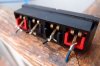
The other thing now is to find (or to build up) the speaker terminals. They came all broken...

And thank you again! I'm following every step here! :thmbsp:
 

Attachments

  • PC290212.JPG
    PC290212.JPG
    94.9 KB · Views: 182
I'm agreement with skippy124 change-out suggestions as well as removing all glue residue - :thmbsp:

The large 10,000uf 50V 4-pin PSU electrolyic caps can be replaced with ones from the Panasonic T-HA Series:

15,000uF 50V 50mm(H) x 35mm(D) - Panasonic part No. ECE-T1HA153EA

12,000uF 63V 50mm(H) x 35mm(D) - Panasonic part No. ECE-T1JA123EA
15,000uF 63V 60mm(H) x 35mm(D) - Panasonic part No. ECE-T1JA153EA

10,000uF 80V 80mm(H) x 35mm(D) - Panasonic part No. ECE-T1KA103EA

I have used the 12,000uF 63V for several AU317 re-caps as they were within my budget.

Nice! Unfortunately this series can't be found easily here in NL. There is a shop selling German made F&T caps (10.000uF 63V) for 15 euros. Do you recommend them?

And some good (not expensive) capacitors (value?) for bypassing with the power caps?
 
Last edited:
Unfortunately I have not come across F&T Caps before, so am unable to comment on these - But looking at their website there are 4pin snap-in types available within their "SI" series (SI4P) (85º up to 5000hrs) - These should be fine as long as they match the existing pin layout of the original. I was able to source the Panasonic T-HA 4pin electrolytics from Mouser Electronics in the US as they dispatch to Europe.

The 1uF 100V polyester bypass caps I used were source from a UK electronics parts retailer for approx £0.20GBP each - My recommendation for the multiturn trimmer pots would be Bourns 3296W series.

Check out skippy124 - Speaker Binding Post Mod for 317/417/517/717 for DIY replacement speaker terminals.
 
Last edited:
AUD101, I believe that the F&T cap I can order is this one.

Thanks for the bypass cap info. I'll take this value. And I'll order the Bourns, too. Shall I order also for those white trims near the heat-sink?
There is a set of speaker connectors on the bay right now see if he will ship.
Oh, thanks! I think I'll try to do it myself a really sturdy connectors... :)

Sorry if I ask too much, folks. It's because I really love this brand and I'm excited with this restoration...

Cheers!

Karl van den Berg
 
Last edited:
F&T make great caps. Purchase with confidence. :)

Skippy's option for mounting binding posts is your easiest 'direct fit' option for a non-standard solution. Otherwise, you can fabricate a Perspex/acrylic mounting plate for binding posts etc.
 
And I'll order the Bourns, too. Shall I order also for those white trims near the heat-sink?

Sorry if I ask too much, folks. It's because I really love this brand and I'm excited with this restoration...

Cheers!

Karl van den Berg

Hi Karl,

The white trim pots nearer the heatsink are the Bias trim pots, and the pairs of trimpots located closer to the front of the amp are for setting the DC offset. These offset pots are set up in a coarse and fine adjustment configuration, so replacing them with multiturns is not necessary from an ease of adjustment view.

And don't worry about asking questions, you will always find plenty of members willing to answer any questions that you may have

Cheers

John
 
F&T make great caps. Purchase with confidence. :)

Skippy's option for mounting binding posts is your easiest 'direct fit' option for a non-standard solution. Otherwise, you can fabricate a Perspex/acrylic mounting plate for binding posts etc.
Thank you, Pete! The only thing now with this new cap is that it is a screw mount cap. Shouldn't be a problem for the connections and bypassing with the other polistirene cap, but I have to build something inside the case to hold it firmly.

And yes, I'll probably follow John's instructions for the speakers' connector!
Hi Karl,

The white trim pots nearer the heatsink are the Bias trim pots, and the pairs of trimpots located closer to the front of the amp are for setting the DC offset. These offset pots are set up in a coarse and fine adjustment configuration, so replacing them with multiturns is not necessary from an ease of adjustment view.

Cheers

John

Oh! So the trimpots I have to order are for the white ones! :thmbsp:
 
It seems that depending on manufacturer most 1N4148 datasheets indicate a Max Repetitive Reverse Voltage (Vrrm) of 75V/100V and Forward Current If (AV) of 150mA/200mA - Which in most situations is OK to replace a VD1212 (2x 1N4148 in series) & 1S2473D (if required).
 
Last edited:
It seems that depending on manufacturer most 1N4148 datasheets indicate a Max Repetitive Reverse Voltage (Vrrm) of 75V/100V and Forward Current If (AV) of 150mA/200mA - Which in most situations is OK to replace a VD1212 (2x 1N4148 in series) & 1S2473D (if required).
Ok! Do you know which board that diode (1S2473D) lay in? I think I'll order a bunch of these... just in case. I'm already restoring the unit and it is completely open now, so if I want to do a good job, I prefer to do everything in one way, then close the unit for some 15 years...

I want to work on some wiring as some of them look not so flexible anymore and the soldering junctions are not shinny at all...

I finally removed the volume pot (pictures below). Took a while, but I discovered why: the hole of the screw was full of dust and other little beasts living inside it. I don't know if this volume pot is the same for the AU-217 and AU-417, but here are some pictures...

Now I'll start working on the other three boards: tone control, equalizer and filter circuit boards.

Thank you!
 

Attachments

  • PC300215.JPG
    PC300215.JPG
    89 KB · Views: 115
  • PC300217.JPG
    PC300217.JPG
    91 KB · Views: 90
  • PC300221.JPG
    PC300221.JPG
    86.8 KB · Views: 91
  • PC300224.JPG
    PC300224.JPG
    89.5 KB · Views: 96
  • PC300226.JPG
    PC300226.JPG
    89.8 KB · Views: 117
Last edited:
For ref:

Head Amp Board – F2751
D1 & D2 - VD1212 - (Replace with 2x 1N4148 in series for each VD1212)

Control Amp Board – F2752
D1 & D2 - VD1212 - (Replace with 2x 1N4148 in series for each VD1212)

Power Amp Board – F2754
D1 & D2 - 1S2473D - (Replace with 1N4148)
D9 & D10 - 1S2473D - (Located under rear of the heatsink) - (Replace with 1N4148)


...and for my own peace-of-mind when I refurb an AU-317 I also replace the Zeners (Have had a couple that drifted off/did not stay anywhere near their nominal value)

Power Amp Board – F2754
ZD601 & ZD602 - EQA01-30R (30V 0.5W) - (Replace with BZX55C30 or 1N5256B)
ZD603 - ZD606 - EQA01-18R (18V 0.5W) - (Replace with BZX55C18 or 1N5248B)


Note that there are two fuse resistors located on the Control Amp Board – F2752 (which are not recorded in the service manual as fuse resistors) which is recommended for replacement - R17 & R18 - 68R 0.5W

Good to hear you finally removed the Volume pot knob - :thmbsp: - The Volume pot knob is shared across the AU-117/217/417 -Just like the other control knobs & switches too!
 
Last edited:
I'll order all of them! :thmbsp:

There's one doubt: there are two electrolytic non-polar capacitors in the Power Amp Board F-2754.

One is 100uF 6.3V NP (C-613) and the other is 1uF 50V NP (C-614) and both are radial caps. These two are not in the Manual Service's schematics.

I could not find them here to sell, but only the 100uF 63V (NP) in axial version for crossover applications.

My question is: being these non-polar caps, is it OK to use some polypropylene or MPK caps? Or those axial caps for crossover suits as well?

Could not find the little 1uF 50V (NP)...
 
Last edited:
My question is: being these non-polar caps, is it OK to use some polypropylene or MPK caps? Or those axial caps for crossover suits as well?

Could not find the little 1uF 50V (NP)...

I note that you are in the Netherlands, so I do not know the availability of replacement parts there.....

That being said, when I re-capped my 317 II last year I was able to order them from Mouser. I happened to use radial BP electrolytics, but I don't see why a film cap wouldn't work for the 1uf 50v position.

I also don't see why you couldn't use an axial BP cap. I've doen it once or twice - I mounted one end flush with the PCB, and sleeved the other end with an insulator and bent it down to the other hole (similar to how Sansui mounts some of their resistors). Worked fine, and looked ok to my eye.
 
Last edited:
The 100uf bipolar should be relatively easy to find, either in Nichicon or Panasonic flavour. You may also be able to buy a few via eBay. I'd suggest stepping up to a 16v rating for these caps if you can.

Regarding the 1uf, I replace all 1ufs (bipolar or not) with Panasonic ECQV stacked film capacitors in 50v or 63v ratings. They are fairly cheap, compact in size, and perform better than any electrolytic in this application. As UB says above, you can fit an axial cap on its end if you wish, but fitting a Panasonic ECQV will be much easier and neater. Some axial polypropylenes have thicker wires and will require the enlargement of PCB holes too.
 
Hi Karl,

I agree with what Uncle Bambi and Pete_mac have advised.

These two caps are in the schematics, look on the right hand side close to the headphone connector. They are part of the protection circuit. Physically these are the two caps closest to the power transformer (upper left on the main PCB when looking from the front of the amp).

I use Panasonic ECQV stacked film for the 1uf 50V caps, including the bipolar one. The 100uf 6.3V bipolar in film may be too large to fit. I get my bipolar electrolytic caps from Partsconnexion in Canada, they will ship worldwide but shipping is not cheap (I usually bundle up a bunch of caps to make the shipping worthwhile).

Cheers

John
 
If you get truly stuck, both BP cap's are available from Farnell-Element 14 (Netherlands)
100uF 50V (BP) - Panasonic ECEA1HN101U
1uF 50V (BP) - Panasonic ECEA1HN010U

The 1uF 50V Panasonic ECQV quoted by pete_mac is also available - Panasonic ECQV1H105JL

I have just noticed from your 1st attached thumbnail pic on post #18 of the Power Amp PCB, that C614 is missing :dunno:
 
I have just noticed from your 1st attached thumbnail pic on post #18 of the Power Amp PCB, that C614 is missing :dunno:
I have already taken it off.

I have a deal with Conrad.nl. They are really cheap and deliver within 1-2 working days. I had problem with Farnell.nl once. I ordered something I don't remember now, they didn't have it in their Dutch warehouse and forwarded my order to Farnell in New Jersey, USA. It took 2 weeks to be delivered and I had to pay an international fee for that.

But, ok, I can order the bipolar axial one (100uF 63V) and the 1uF in film.

Bellow, more pictures of how things are proceeding... From how it came inside (spiderwebs, and dust, dust, dust!!!) to how it is now...

I took ALL the pots off, open the volume pot and cleaned inside. Did some wiring job, de-oxided the line RCA connections, cleaned and reassembled the speakers selector and re-soldered its cables, Tone and High Filter switches also deep cleaned, same with Loudness and Tape Monitor switches. Cleaning of all the metal structure...

At the end I will call this integrated Sansui AU-317 M-AK3 :beerchug:
 

Attachments

  • PC310239.JPG
    PC310239.JPG
    93.1 KB · Views: 187
  • PC310238.JPG
    PC310238.JPG
    95.2 KB · Views: 193
  • PC280132.jpg
    PC280132.jpg
    87.9 KB · Views: 181
  • PC280125.jpg
    PC280125.jpg
    75.8 KB · Views: 190
Hi folks! The "new" AU-317 is on the way! I'll post pictures when it's completely done.

However, first, I'd like to ask if can change safely its power cord to a more robust grounded one.

The "original" (2nd picture) is not that robust anymore and I'm afraid it will break in the case sometime.

I want to put a 250V 10A with the yellow wire (1st picture) and ground it at the amp's chassis. Is there anything I have to avoid with the AU-317??

Thanks again!
 

Attachments

  • P1040276.jpg
    P1040276.jpg
    31.6 KB · Views: 79
  • P1040277.jpg
    P1040277.jpg
    28.1 KB · Views: 74
Back
Top Bottom