

You are using an out of date browser. It may not display this or other websites correctly.
You should upgrade or use an alternative browser.
You should upgrade or use an alternative browser.
Hmmm... That can't be good!
- Thread starter Redboy
- Start date


Register to hide this ad


soundmotor
super modified
Smoke 'em if you got 'em!

Redboy
a few good watts
None other! I'm holding out hope that the trannys didn't go when the resistor lit up. They look pretty good and don't show any signs of major meltdown. I might have a pro check them out before I sink much into this.Is that the Pilot?
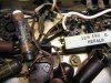
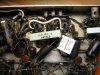
The odd thing? It's pretty obvious that someone did some work in here at one point. I've got to believe it was before the fire (maybe caused the fire?) but the replacement parts look un-roasted. It's all a little weird.
If the iron passes the test, I think I'll do a complete rebuild.


"Toast is ready!"
I'm sure you're up to the task. It's winter, what else is there to do?
I'm sure you're up to the task. It's winter, what else is there to do?


Looks like you can trace where the resistor was and where in the circuit it could drawn too much current.
That is always a help. Then pull tubes and check open circuit voltages.
Took a second look. One end is attached to a lug of the multicap. When they start to go, they draw too much current through the rectifier. Looks like it passed a little too much to where ever this resistor goes.
And all tube types I work on get a grounded plug and a CL-90 thermistor in the power wire.
Redboy
a few good watts
No worries, Jay! I'm getting excited about the challenge of a total rebuild, so I'm really hoping the iron checks out.Sorry bout the boat anchor comment, I didn't know it was a valuable piece.
You said to "ohm out" the outputs... could you spell that out a little for a novice?

jaymanaa
RIP 1961-2018
I think so, is it PP?For the OPTs you should be able to measure "some" resistance from the center tap to each tail, then tail to tail should be twice that. On the output side you should get "some" resistance from common to 8ohm, common to 16 ohm, etc. This should let you know if a winding is open, then I would check resistance from each lead to the lamination stack. That will tell you if anything is shorted to the stack. Why don't you post your readings here too.

Just looking at that, the resistor that cooked goes right off one side of the filter cap. I'd bet you a donut that filter cap is shot, and it probably took out the resistor. Whats the other end of it connected to, one of the rectifier tubes? If so, that would make sense. If I had to guess, I'd say probably the trannys are fine, but possibly the diode took a hit.
Similar threads


- Replies
- 42
- Views
- 1K


