• Please note that Audiokarma will be offline briefly for updates early on Monday morning, September 28th.

12 AWG Speaker Wire with an Impedance of 100Ω - 150Ω

Ladder line, open wire, twin lead, all are too high in impedance for my purposes, and they don't have the physical characteristics that I need, which is that the wire insulation serve as the spacing mechanism. I'll try the 12 AWG speaker wire I have. My load is nominally 120Ω (~95Ω on the lower frequencies, 145Ω on the higher frequencies) and 12AWG speaker wire will handle the voltage I plan on applying without the insulation breaking down. When I get a chance, I'll test the impedance and post my results for anyone who cares.
Ok, but like I thought I typed, that I seem to remember the ~1" in width spacing ladder line that I saw offered in a Ham radio catalog in the eighties was fully insulated with the molded window gaps between the wires every so many inches spacing down the length, not the higher power rated twin line open type with dog bone design insulator wire separators spaced every so many inches.
I don`t remember the characteristic impedance of the advertised fully insulated commercially available ladder line, as my "DC to Daylight" wideband radio receiving hobby pursuit`s interests at that time, didn`t involve that feed line technique !
 
IIRC (it's been a long time) the characteristic impedance is mainly function of distance between conductors - (about 1/2 inch for 300 ohm twin lead). So spacing of the two wires is primary concern for your project. My 2 cents.
 
funny or not: I use clear see through speaker wire one has a silver color as part of the strand connected together plastic two wrapped next to each other together 10' long for each I've had for 25-30 years old. I think if you have to figure it down to the ohms in length of wire it's kind of crazy to me. Im old school guy using tube pre amp to two tubed mono blocks to Altec Lansing 10 cubic ft cabs at 150 lbs each cab.
 
Last edited:
If I remember correctly back in the fifties and sixties there was 72 Ohm cable (not 75 Ohm to my recollection) that was a paralleled conductor cable that looked just like the typical figure 8 cable used as cheap speaker cable today...the 300 Ohm and 450 Ohm had wider spacing and usually cut out windows for the typical ladder line look and a reduction in losses.

The impedance is set by the spacing....having the wrong match even on a balanced line, can lead to unwanted radiation in transmitting and unwanted losses in effective coupling an antenna to the transmitter/receiver...played a lot with that stuff 30 years ago...

What works at RF is quite different from what works at AF
 
I remember using two paralleled sections of coax as a matching section to match the characteristic impedance of an antenna to that of the feed from the transmitter's 50 Ohm unbalanced output...maybe paralleling two RG-8 Mini with the shields tied together at each end would give you a balanced transmission line of an impedance closer to what you need?

I'm at work or I'd go through some of my old ARRL Radio Amateur's Handbooks and antenna books to see what they have to say.
 
I remember using two paralleled sections of coax as a matching section to match the characteristic impedance of an antenna to that of the feed from the transmitter's 50 Ohm unbalanced output...maybe paralleling two RG-8 Mini with the shields tied together at each end would give you a balanced transmission line of an impedance closer to what you need?

I'm at work or I'd go through some of my old ARRL Radio Amateur's Handbooks and antenna books to see what they have to say.
Thanks for the idea, but I do need a wire where the two conductors maintain a relatively stable distance apart, and speaker wire fits the bill, it's just that I was looking for a brand/model, that could give me ~100 Ohms or so. And I found one that, by the stated dimensions should be reasonably close. I spend $46 on 250', which is perfect for experimenting.
 
Ok, but like I thought I typed, that I seem to remember the ~1" in width spacing ladder line that I saw offered in a Ham radio catalog in the eighties was fully insulated with the molded window gaps between the wires every so many inches spacing down the length, not the higher power rated twin line open type with dog bone design insulator wire separators spaced every so many inches.
I don`t remember the characteristic impedance of the advertised fully insulated commercially available ladder line, as my "DC to Daylight" wideband radio receiving hobby pursuit`s interests at that time, didn`t involve that feed line technique !
I remember 4-inches being golden, for reasons I've long forgotten. :)
 
During my DX days, I ran Alpha-Delta Sloper long wire antenna with a 6-foot "ladder" section. I used a 50-ohm impedance coax cable.

It is the best faint signal grabber I have ever used.
Didn`t Zep offset long wire dipole antennas strung beneath the air ship use open air ladder type transmission line ?
 
Didn`t Zep offset long wire dipole antennas strung beneath the air ship use open air ladder type transmission line ?
Did you listen to a long-distance shortwave?

I heard a Pidgin English news report about the Queen's imminent visit to Tonga. I tried getting a DX card, but it never got mailed. It was the highlight of my listening hobby, and I wished I had recorded it.
 
Did you listen to a long-distance shortwave?

I heard a Pidgin English news report about the Queen's imminent visit to Tonga. I tried getting a DX card, but it never got mailed. It was the highlight of my listening hobby, and I wished I had recorded it.
Yes, from DC (5kHz ~ Day light (or 2.5 Gig.), higher frequencies if you count my C/Ku big dish scoping out wild feeds from all the Networks.
I also DX`d NTSC VHF~UHF distant reception, as far away as Mexico to stations all over the SE United States when springtime Tropospheric ducting opened the paths.
And video taped the station`s call letter IDs. And invited my doubtful un technical savvy fellow pot smoking friends to drop by late April afternoons to see for them selves as the cooler air started descending over the warmed up earth in the path.

I bought the top of the line ultra fringe separate Channel Master VHF and UHF antennas with their best performance mast mounted frequency band specific preamps using the lowest loss Belden stranded center 75 ohm coax with a rotor for each separate 50 foot Rohn brand pushup telescoping pole, with variable 75 ohm attenuators so not to overload the more nearby TV stations reception to my VCR`s already sensitive frontend ~ 50 miles from my parent`s rural located house where I was living with the poles attached to the opposite corners of a 12`X12` shed on their property where I spent my waking hrs. re-teaching myself how to repair audio/radio equipment with the use of one hand/arm.
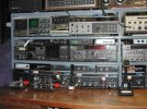
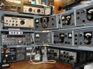
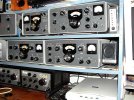
I thought you saw my posted pictures of my DC to Daylight multi receiver suite behind where I sit typing on A/K everyday.
No cable TV for yrs later at parent`s house so I wanted to pull in as much remotely located TV choices as possible to keep from being bored, and it was a technical high frequencies atmospheric moisture rich path loss challenge, especially at the higher UHF TV channel frequencies !
 
Whoa! It's a way more sophisticated setup than my little computer room - radio shack. What equipment did you use?

I had a JRC receiver and a portable Sangean.
 
1734332857685.jpeg
1734332907377.jpeg

1734332953521.jpeg

I enjoyed DX'ing, OSCAR/Ham sat operating, restoring old gear, running AM with the BC610 in the closet and R390 and 51J4 receivers...those pictures are about half of what's in my "shack"...

I do keep my grandfathered Advanced class license up to date.
 
If I remember correctly back in the fifties and sixties there was 72 Ohm cable (not 75 Ohm to my recollection) that was a paralleled conductor cable that looked just like the typical figure 8 cable used as cheap speaker cable today...the 300 Ohm and 450 Ohm had wider spacing and usually cut out windows for the typical ladder line look and a reduction in losses.

The impedance is set by the spacing....having the wrong match even on a balanced line, can lead to unwanted radiation in transmitting and unwanted losses in effective coupling an antenna to the transmitter/receiver...played a lot with that stuff 30 years ago...

What works at RF is quite different from what works at AF
All I can say is will a bit of volume I can hear the horse hair on a cello, if I'm playing metallica I feel like I'm right on stage with them all around me that's half volume on power amp 1/3 on tube pre amp with 4 tube active EQ and p/p tube 6550's 1959 amps 10 hz - 20K hz
 
All I can say is will a bit of volume I can hear the horse hair on a cello, if I'm playing metallica I feel like I'm right on stage with them all around me that's half volume on power amp 1/3 on tube pre amp with 4 tube active EQ and p/p tube 6550's 1959 amps 10 hz - 20K hz

That's audio, RF behaves a bit differently, with audio we don't worry much about parasitic losses, mis-matched impedances, RF radiating from the feed line, velocity of propagation, VSWR, etc., horses for courses....
 
That's audio, RF behaves a bit differently, with audio we don't worry much about parasitic losses, mis-matched impedances, RF radiating from the feed line, velocity of propagation, VSWR, etc., horses for courses....
well when i read the title i wasn't aware if it was about speaker wires or not until i saw all the photos of all the great looking radio stuff related to the title. my mistake sorry guys ...
live and learn.
 
Back
Top Bottom