• The move to the new server is done. There are some software and database maintenance updates in process. This has us passing the hat around to help out. We appreciate any donations. Seriously, even a dollar helps. The payment page may be found here - https://www.audiokarma.org/support.html

2252B power/amp brd issues

mgl99

Active Member
I've run into a problem with this 2252B. I've been working on it for quite a number of hours. When I first got it, I inspected it inside, and figured it safe to energize. When I did, the protection relay closed in and everything seemed normal.

I then recapped all of the boards, including the power/amp board. I noticed several caps soldered onto the back of several boards. Apparently, this is where I made my mistake. I removed them as I thought they were "band-aids" applied by someone else in the past. Big mistake! I found out by hours of research, including this forum, that these components were part of a factory mod during production.

Fortunately, I always take many pictures while I go through a unit. I have now reinstalled the 0.47 mfd film cap @ 50V. I have reinstalled all but two caps, but they are .047 mfd. I don't have clear enough pics and I have seen nothing of these two caps on any youtube vids.

I have replace all of the diodes, including the "Varister" tantalums (two 1n4148s in series), as well as all of the electrolytic caps. I am also aware that C701 polarity is marked incorrectly on the PCB. I have replaced all resistors that appeared overheated, such as R721. I also replaced others.

The protection relay has also been replaced. Biggest problem is, I have no time to take any readings because when I energize it I get smoke!! This time it was R707 1k ohm 1/4 w. R708 1k ohm @1/4 w was not affected, at least visually.

There is no time for the protection relay to even close in! I have carefully inspected all solder joints and re-melted any and all that looked suspicious. I have taken readings on all remaining resistors on the board with my ESR meter. They all appear to be good with 10 percent. I have also tested the output transistors using my DCA 55 meter. They test good, but of course that isn't under power.

Since I hate seeing smoke, I'm getting a little gun shy of shooting in the dark here. Help please!!!
 
Register to hide this ad
Tomorrow, I'll see if I can snap a photo of the trace side of the P700 Main Amp/Power Supply board. If they are way under the two main electrolytics, I'm not sure you will be able to see it and they are a pain to remove.
 
Ok, the only components that I have on the underside of the 2252B P700 PCB are the following (unless there is something under the two switch lever arms that I can't see. Let me know if you need anything else.

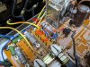
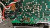
1. (1x) 0.047uF capacitor
PXL_20230210_161442391.jpg

2. (1x) 47uF 50V electrolytic capacitor
PXL_20230210_161506367.jpg

3. (2x) 470ohm (YEL-PUR-BRN) resistors
PXL_20230210_162445507.jpg

I really need to clean up the flux on these.
 
On another note, my 2252B seemed to be missing a resistor in series with the diode by the relay. This caused the voltage across the relay coil to be high (about 30V if I remember correctly) and both the diode and relay were getting pretty hot. Adding the 100ohm/2W in series with the diode dropped the voltage to 24V. @rBuckner checked his 2252B and it did have this resistor added.
InkedPXL_20211011_040653971_LI.jpg
 
Hmmm... There are also these areas, but I can't tell if there is anything under the flux unless I clean it up. (It came like that, not my work)

PXL_20230210_165706147.jpg

PXL_20230210_165654885.jpg
 
Thank you for the pics. I have verified that I have the right connections for the added factory components. I have already replaced the 100 ohm resistor and series zener diode. for R776. I have also replaced 12 resistors. I have pulled and tested all transistors on the board. I found Q705 to be bad. I replaced the 2sc1885 with a KSC2690AYS. I also changed out Q706 the same way. I replaced the prot. relay with a new OMRON MY4-02 24 VDC.

I can now energize the board without having smoke. It seems nothing is overheating, but I now have 38.4 v on BOTH sides of the relay coil, (ie no potential). The protection relay does not close. I have been able to set the B voltage to exactly 35.0 VDC (J722 to ground). I have also verified that I have 30 VAC coming in to J705. BTW, it looks as though others have used a 1N4004G zener in series with the 100 ohm resistor for R776. I'm going after it again today, but I sure could use a little help.
 
Thank you for the pics. I have verified that I have the right connections for the added factory components. I have already replaced the 100 ohm resistor and series zener diode. for R776. I have also replaced 12 resistors. I have pulled and tested all transistors on the board. I found Q705 to be bad. I replaced the 2sc1885 with a KSC2690AYS. I also changed out Q706 the same way. I replaced the prot. relay with a new OMRON MY4-02 24 VDC.

I can now energize the board without having smoke. It seems nothing is overheating, but I now have 38.4 v on BOTH sides of the relay coil, (ie no potential). The protection relay does not close. I have been able to set the B voltage to exactly 35.0 VDC (J722 to ground). I have also verified that I have 30 VAC coming in to J705. BTW, it looks as though others have used a 1N4004G zener in series with the 100 ohm resistor for R776. I'm going after it again today, but I sure could use a little help.
Quick observation: 1N4004 is a rectifier type diode, not a zener type diode. I'm pretty sure it's some value of zener in series to lower the coil voltage, not a 1N4004. The 2252B was a customer's unit, I only had pictures from when it was here so I can't go open it up to look at it. Well, not without travelling somewhere to do it! :biggrin:

EDIT 2/25: I was wrong, it is not a zener diode but a rectifier diode and a 1N4004 will work great.
 
Last edited:
Thanks for all the input. Now I'm wondering if the 1N4004 is wrong. I do have the original diode that was in there. It looks very much like all of the "original" pictures show. It looks like the other WO6 diodes on the board. According to the Marantz substitution post, the WO6 is replaced by a 1N4004. However, it might be better to use the original (which tests good) rather than the 1N4004. Regardless, I did have a 100 ohm 1W resistor in series for R776. The other thing is, that I do not list Q754 on the parts list in the service manual. It doesn't tell us what type of diode it's suppose to be. I could not perform the amplifier voltage adjustments as there is nothing there (0 V) on either side.
 
You should be fine with the 1N4004, but please verify a couple of things:
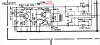
  1. From connector J705 it goes to the diode (1N4004) Anode, then the diode Cathode (band) goes to the 100 ohm resistor.
  2. The 100 ohm resistor then goes to one side of the relay coil and also the Cathode (band) of Q746 and the (+) side of capacitor C740.
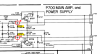
  3. With you DMM, measure the AC & DC voltages at the following locations:
upload_2023-2-22_9-17-13.png
4. Since the relay is not energized, you may not get these voltages. Then you would need to check the transistor EBC DC voltages first. Report these voltages.​
 
Also, please verify that you have the 10uF electrolytic capacitor (C740) soldered to the back of the PCB.
 
Here is what I have done. First off, I changed R776 to a 100 ohm 2 watt resistor in series with the original diode that tests good. Yes, it is connected as you have described and as shown in your attached pics. This is how it was originally, with the exception of installing a 2W 100 ohm resistor. The C740 cap is a 47 uF @ 50 V, and it is connected exactly as shown in your pic. The connections you describe are all as I have them. They are correct.

Here is the voltage information you requested:

At the Anode of the diode (input from J705): 29.22 VAC 0 VDC

Between the Cathode and the resistor (100 ohm 2W): 12.85 VAC 38.24 VDC

Opposite end of resistor (goes to one side of relay coil): 10.76 VAC 38.11 VDC

Here are the readings on the Q743, Q744, & Q745:

Q743 (2SC945)

E C B
0.2 mVDC 11.7 mVDC 0.723VDC

1.0 mVAC 1.0 VAC 1.0 mVAC

Q744 (2SC945)

E C B
46.0 mVDC 38.3 VDC 11.7 mVDC

354.0 mVAC 7.64 VAC 1.0 mVAC

Q745 (2SC1318)

E C B
37.0 mVDC 38.3 VDC 0.1 mVDC

331.0 mVAC 7.1 VAC 1.0 mVAC

One other point of interest is that while taking the ECB measurements, my probe apparently slipped a little, and shorted the E and C legs of Q745. The protection relay went closed, and as soon as I withdrew it, the relay went open. I didn't want to burn up the coil, but it's nice to know the new relay works. One other thing, you wanted to know the voltages across the relay coil.

You also wanted to know the voltages across the protection relay coil. If I understand the schematic correctly, this would be readings across Q746, which spans the coil contacts. Here are the VDC readings: Q746 Cathode end: 38.47 VDC
Q746 Anode end: 38.35 VDC. This has been the problem since recapping. I have double checked all electrolytic cap polarities, and yes, I know about C701.

If I have forgotten info, or you need additional info, please ask. I'm trying to figure out why the excessive voltage. Your help is greatly appreciated, as always.
 
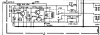
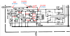
Here are your voltages on the schematic:
upload_2023-2-23_12-45-37.png
The relay isn't turning-on because Q745 (C) is at 38.3v, it should be 3.1v. This is because Q745 (B) is at 0v instead of 0.7v so the transistor is turned-off.
Q744 needs to turn-on to raise the voltage at the emitter to >0.6v (it is now at 0v). The collector of Q744 is at 38v because it is not turned-on, because Q744 (B) is at 0v instead of 1.3v.
Q743 (C) is at 0v when it should be at 1.3v. This is because it is turned-on and conducting. It is turned-on because Q743 (B) is at 0.7v (too high) vs 0.04v.

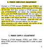
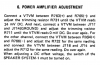
First, try to perform this Power Amplifier Adjustment. See the last sentence about the Speaker System 1 switch must be turned on to perform.
Make a note of the voltages before and after you adjust for comparison. The relay is not engaging because of the voltages to A743.
upload_2023-2-23_13-29-53.png
The other thing is that I am not sure why you have so much AC voltage after the diode and 100 ohm resistor?
 
Sorry my post was difficult to read as it removed my spacing, but apparently you deciphered my readings. I will do the power amp adjustment this morning.
 
I attempted, once again, to perform the power amplifier adjustment. R731 and R732 have no affect on their respective channels. The highest mVDC achieved was 4.4 mVDC and 3.0 mVDC , respectively. I did not go on with the second step of each channel, as it seemed unnecessary. There must be a reason as to why +38.4 VDC is appearing where I should have 23.0 VDC, as well as affecting Q743, Q744, and Q745, of course.
 
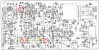
Could you please post a photo of the top side of the board and indicate which components you replaced.
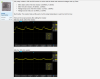
Did you say that you do have an oscilloscope? If yes, can you post a photo of the waveform after the diode and also after the 100 ohm resistor.
Thanks.
 
I attempted, once again, to perform the power amplifier adjustment. R731 and R732 have no affect on their respective channels. The highest mVDC achieved was 4.4 mVDC and 3.0 mVDC , respectively. I did not go on with the second step of each channel, as it seemed unnecessary. There must be a reason as to why +38.4 VDC is appearing where I should have 23.0 VDC, as well as affecting Q743, Q744, and Q745, of course?
 
Back
Top Bottom