Yes, that is where I connected the probes. I am for sure not the most knowledgeable, but this is the eighth Marantz receiver I have worked on. The others, (3) 2265, (2) 2270, and (2) 2275, are working perfectly. Still, I have not encountered what I am finding here. Please bear with me, but I have done a few voltage adjustments to these receivers. There is no control of voltage from R731 or R732.


You are using an out of date browser. It may not display this or other websites correctly.
You should upgrade or use an alternative browser.
You should upgrade or use an alternative browser.
2252B power/amp brd issues
- Thread starter mgl99
- Start date
-
- Tags
- 2252b power supply issues
I attempted, once again, to perform the power amplifier adjustment. R731 and R732 have no affect on their respective channels. The highest mVDC achieved was 4.4 mVDC and 3.0 mVDC , respectively. I did not go on with the second step of each channel, as it seemed unnecessary. There must be a reason as to why +38.4 VDC is appearing where I should have 23.0 VDC, as well as affecting Q743, Q744, and Q745, of course?
Yes, I attached them at the correct points. Though I am far from an expert, this the eighth Marantz I have done. The others (all mine) (3) 2265, (2)2270, and (2) 2275), are all working very well. I have done a few adjustments in this area, and I know I am testing correctly. This is the first time I have run into these problems. It's a learning experience for me, but I do know how to test. It's interpretation of the results where I hope to get educated. I still don't understand what the cause of the high DC voltage is.

Could you please look at the voltage at the emitter of Q715/Q717 and Q716/Q718. It should measure 0v. IF not 0v, then I think you can adjust R711 and R712 to make it 0v per PA Adjustment directions. The only difference is that you cannot use the test points since they are on the other side of the relay.
NOTE: You need to have your Speaker 1 switch ON.
NOTE: You need to have your Speaker 1 switch ON.
Yes, I did test at the correct points. I am far from an expert, but I have enough experience that I can tell you, the values I have given you were taken correctly. I took the readings exactly as directed in the service manual. I read the values across the resistors. The service manual doesn't say to test from resistor to chassis ground, so I didn't do that. I also took some pictures as you requested, but it has been a number of years since I've uploaded pics to AK. I could use a reminder on how to do that. Also, I do have an oscilloscope.
I will also get the additional readings you mentioned.
I will also get the additional readings you mentioned.
Last edited:
To upload a photo do this:it has been a number of years since I've uploaded pics to AK. I could use a reminder on how to do that.
- Make sure your photo is of type *.jpg, *.png, *.gif, or *.pdf.
- Click on the "Upload a File" button on the lower right of the message box
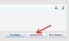
- Navigate to your file and select it.
- Below the message you will get a box that asks if you want to insert a Thumbnail or Full Image... select Full Image.
That's fine, I was just double checking to make sure you measured the DC voltage across both resistors and not just one.The service manual doesn't say to test from resistor to chassis ground, so I didn't do that.
That's good, and I can assume that you already know how to use it to make measurements? Is it a digital scope or analog CRT scope?Also, I do have an oscilloscope.
- What I would like to see on the oscilloscope (set to DC input) are the waveforms after the rectifying diode Q754 and after the 100ohm resistor.
This is just conjecture, but I believe that the relay does not engage because (as you correctly mentioned) the voltage at the relay is not correct. We need to investigate this.I still don't understand what the cause of the high DC voltage is.
- As explained in Post #15, I believe the relay is not engaging because the state of the transistors is not correct.
- It goes back to the Q743 Vb being 0.72V vs the expected 0.04V. This is enough to turn on the transistor, which is (I think) what happens when you have a fault condition and the relay turns off to protect the amplifier and speakers.
- The goal was to isolate and determine why this voltage is incorrect.
- This is what I would like you to measure, but you can't measure it at J717 because the relay is not engaged.
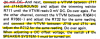
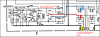
- We need to follow the signals up to where they go between the two transistors and verify 0VDC.
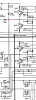
- If this is not 0V, then check to see if R711 & R712 can bring it to 0V.
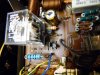
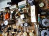
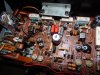
Okay, before I attempt posting pics, here are the readings you wanted. Q715 Emitter voltage 37.0 VDC. Q717 Emitter voltage 37.0 VDC. Q716 Emitter voltage 37.47 VDC. Q718 Emitter voltage 36.73 VDC. Also R711 and R712 had no effect in
changing the voltage on either emitter voltage to Q715 and Q717 , or to Q716 and Q718.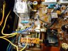

changing the voltage on either emitter voltage to Q715 and Q717 , or to Q716 and Q718.

My bad some posts back on that diode. It is NOT a zener and a 1N4001 would work fine. It rectifies an AC transformer voltage to run the relay.
The voltages all being way positive would be why the relay won't engage. I wonder if there is no negative supply voltage is getting into the board. It should be over -40V on two of the output transistor cases, one per channel. That would be Q711 and Q714, the PNP ones (2SA743). Maybe a busted wire or connector pin J708 solder joint cracked.
The voltages all being way positive would be why the relay won't engage. I wonder if there is no negative supply voltage is getting into the board. It should be over -40V on two of the output transistor cases, one per channel. That would be Q711 and Q714, the PNP ones (2SA743). Maybe a busted wire or connector pin J708 solder joint cracked.
I read the thread again and was wondering about the smoked 1K at R701. It may have taken out one or both of the two small transistors in the first stage (diff pair). That would be Q701 and possibly Q703. A great replacement for here would be KSA992's, best if matched as close as possible in gain with whatever you have on hand. Marantz didn't match them so it's not mandatory.
I didn't say anything about R701. What I said, was that it was R707 that had burned up (1k @ 1/4W). I then said, that I had recapped the board, and that I was well aware that the polarity markings on the board are incorrect for C701. I will get additional readings this morning. I want to re-iterate that there is +38 VDC on both of the PR coil terminals. Yes, I would say that there is no negative voltage at the relay coil. This has been the problem all along, but why?
I want to re-iterate that there is +38 VDC on both of the PR coil terminals.
@mgl99 Please re-read my explanation in Post #15 as to why there is 38V on both relay terminals. It is off because Q745 is turned-off (Vb = 0v) so the there is no collector to emitter current flow. This means no current flow through the relay coil since both sides of the coil are the same voltage. No current through the coil also means that there is no voltage drop through the 100ohm resistor causing the 38v at the relay vs 24v that it should be.This has been the problem all along, but why?
Also, please check J708 for -41V.
Last edited:
Just one more thing to check (and you probably did it right, but I can't tell from your photos) is for the main 10,000uF filter caps, did you wire the ground connection (black wires and buss bar) to one of the caps to the (+) terminal and the other to the (-) terminal?
Yes, of course I did. Here are the voltage readings folks requested:
J708 , reads - 38.62 VDC (negative 38.62 VDC) to chassis GROUND.
All readings, unless otherwise directed by procedure, and so noted, will be
to chassis GROUND.
Q701
E 0.582 VDC
C -38.42 VDC
B 0.5 mVDC
Q703
E 0.579 VDC
C -38.61 VDC
B 9.63 VDC
I also took voltage readings on the main output transistor COLLECTORs to chassis ground:
A753 (both channels) -38.92 VDC
C1343 (both channels) 38.75 VDC
J708 , reads - 38.62 VDC (negative 38.62 VDC) to chassis GROUND.
All readings, unless otherwise directed by procedure, and so noted, will be
to chassis GROUND.
Q701
E 0.582 VDC
C -38.42 VDC
B 0.5 mVDC
Q703
E 0.579 VDC
C -38.61 VDC
B 9.63 VDC
I also took voltage readings on the main output transistor COLLECTORs to chassis ground:
A753 (both channels) -38.92 VDC
C1343 (both channels) 38.75 VDC
NEW DEVELOPMENT (not good)
I energized the unit and took the readings, after about 5 mins, I noticed smoke. I was writing at the time and had the probes nowhere near the chassis. I immediately killed power. It was R703 (33 ohm). This is one of the 1/4W resistors that I had replaced early on. I thought that it had been due to the fact that I had landed a lead wrong on the "added" .47 film cap, (not the polarized cap) on the back side of the board. I replaced it and R701 with new 33 ohm 1 W resistors. No trouble after that, until now. I don't know how much burning up this board can take. Another development, I went and took a closer look at everything after writing my reply. R728 (22 ohm 1W ) has signs of overheating as well. This is another resistor that I had replaced earlier on.
Here are readings that I did get.
J708 -38.62 VDC to GRND
Q701
E 0.582 VDC
C -38.42 VDC
B 0.5 mVDC
Q703
E 0.579 VDC
C -38.61 VDC
B 9.63 VDC
I was going to take ECB readings on other transistors, but got smoked.
I energized the unit and took the readings, after about 5 mins, I noticed smoke. I was writing at the time and had the probes nowhere near the chassis. I immediately killed power. It was R703 (33 ohm). This is one of the 1/4W resistors that I had replaced early on. I thought that it had been due to the fact that I had landed a lead wrong on the "added" .47 film cap, (not the polarized cap) on the back side of the board. I replaced it and R701 with new 33 ohm 1 W resistors. No trouble after that, until now. I don't know how much burning up this board can take. Another development, I went and took a closer look at everything after writing my reply. R728 (22 ohm 1W ) has signs of overheating as well. This is another resistor that I had replaced earlier on.
Here are readings that I did get.
J708 -38.62 VDC to GRND
Q701
E 0.582 VDC
C -38.42 VDC
B 0.5 mVDC
Q703
E 0.579 VDC
C -38.61 VDC
B 9.63 VDC
I was going to take ECB readings on other transistors, but got smoked.
Last edited:
