• The move to the new server is done. There are some software and database maintenance updates in process. This has us passing the hat around to help out. We appreciate any donations. Seriously, even a dollar helps. The payment page may be found here - https://www.audiokarma.org/support.html

2252B power/amp brd issues

I didn't say anything about R701. What I said, was that it was R707 that had burned up (1k @ 1/4W). I then said, that I had recapped the board, and that I was well aware that the polarity markings on the board are incorrect for C701. I will get additional readings this morning. I want to re-iterate that there is +38 VDC on both of the PR coil terminals. Yes, I would say that there is no negative voltage at the relay coil. This has been the problem all along, but why?
Oops, I typed R701 but it was R707 that I was looking at to ask about the diff pair.

R703 is 33K on the schematic and in the parts list. Even if it connected to 40 volts plus or minus, it wouldn't smoke. You measured near zero volts at the base of Q701 so is that resistor the one you think or is it really connected there? Q701's base, if shorted to the collector, and so at -40V would smoke a 33 ohm though. But that transistor would be through! Something's not connected as it should be regardless is my suspicion.

The base of Q703 is most likely due to the output of the amp being at a substantial positive voltage. I bet it is fine and a simple diode test will verify that. That voltage is due to the feedback path via R719.
 
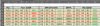
Updated: As best I could from your photos and the photos I had of my 2252B, I assembled this resistor comparison list.
It was a little difficult to see the color bands from your photos. If I made a mistake, please correct me.
upload_2023-2-26_18-37-30.png
Please double check this against your actual boards.
 
Last edited:
First off, I'd like to thank everyone for hanging in.The problems pointed out were real, with exception of R776. I checked it with the meter before soldering it to the diode. I also checked it again today. It is correct. I always use a meter especially with the blue colored resistors. It throws the band colors off, so I verify with the meter. So, why did I get the wrong resistors in other spots (and they weren't blue). Because I had a brain fart and didn't pay enough attention to detail in reading the numbers, such as missing decimal points and tiny "k" symbols. In other words, I screwed up.

After all day correcting things here is the current status. All of the resistors have been corrected and verified, and verified, and verified. Including R768, which is suppose to be a 2.2 ohm. I had replaced it with a 22 ohm. This also, has been corrected. After inspecting all other resistors visually and with meter where possible, I decided to energize it.

I did, and just let it run while observing signs and temperatures. After 30 mins. I started taking readings. I checked "B" voltage at 35.0 volts. I then read across R763 (+) and R765 (-) and found 5.8 mVDC. I attempted to adjust R731 and it has no effect. I attempted adjusting R711 with no change.

I then went to the other channel (Left) and read across R764 (+) and R766 (-). I found 18.5 mVDC and was able to adjust it to 24.0 mVDC using R732. I then read across J718 and J714 and found 0.1 mVDC. Problem there is that R712 had NO effect. The reading remained at 0.1 mVDC regardless of the position of R712.

Yes, I had Speaker 1 selected to ON for all of these amp readings.

I did take ECB readings on Q743, Q744, and Q745.

Q743

E 0.1 mVDC

C 0.648 VDC

B 0.696 VDC

Q744

E 44.0 mVDC

C 38.6 VDC

B 11.7 mVDC

Q745

E 0.1 mVDC

C 38.6 VDC

B 42.5 mVDC

Well, I started getting tired and certainly didn't want to make any more mistakes. Things still aren't right, so I'm sure I'll be taking more readings in the morning. Thanks again to everyone helping me.
 
Well, you still have an amp channel with a high positive dc offset - or both. The Q743 base at about 0.7 tells me that. You can tell which amp(s) by measuring the dc volatge at the ends of R769 and R770 away from the junction of the two. That's what we need to know next.
 
This is what I measured: I put the Neg probe on the far end of R769, and the Pos probe on the far end of R770, My meter read +38.4 VDC. I had replaced both R769, R770 (both 5.6k ohms). I also replace R768, as stated in a previous post, because I had installed a 22 ohm rather than 2.2 ohm. I corrected that. After the previous mistakes with resistor replacements, I also verified these as well as all the others I had replaced. Why did I get some control over the LEFT channel (R712 still has no affect), and still have no control over the RIGHT channel ( R731 and R711)?
 
I think that you misunderstood. What @rBuckner wants you to measure is the voltage from the resistors to Gnd as shown in this schematic. They should be approx. equal unless one side is drawing much more current.

upload_2023-2-28_10-43-39.png
 
Here are some additional readings I just took: (all readings taken to GRND)

Q701

E -38.85 VDC

C -38.93 VDC

B -38.84 VDC

Q703

E -38.84 VDC

C -38.87 VDC

B -29.63 VDC

Q705

E -37.81 VDC

C +38.33 VDC

B -37.75 VDC

Q706

E -37.60 VDC

C -1.27 VDC

B -37.60 VDC
 
I think that you misunderstood. What @rBuckner wants you to measure is the voltage from the resistors to Gnd as shown in this schematic. They should be approx. equal unless one side is drawing much more current.

View attachment 2813416
Yes, you marked up the schematic correctly. With 0.7 volts on the base of Q743, I wanted to know which channels(s) it was coming from and the measurements show neither! With the last measurements posted on that Q743, I wonder if there is a short between the collector and base? Either the transistor itself or a solder short.

But then again, Q743 collector is connected to Q744 base and you have two different readings for those points so maybe my analysis is wrong. the measurements of the ends of R769 and R770 to each other should've yielded a near zero value with what was posted after from those spots to ground.

Sorry but it's hard to figure out this mess with conflicting info. You don't live near me in Az. do you?
 
Last edited:
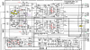
On the schematic. New measurements are in purple, prior values are in green.
upload_2023-2-28_18-49-47.png

Some observations with the new measurements:
  • Q701 & Q703 look like they have a short between either B to C or B to E. Both base voltages are way negative.
  • Both have a high and negative, Ve = -38.85v.
  • Q705 has a +38.33v and should be negative.
Might I suggest that we determine the extent of the damage by measuring the EBC of Q715, Q717, Q707, Q709 for one channel. Then EBC of Q718, Q716, Q710, Q708 for the other. Then maybe we can isolate the issue to just the first stage of the amp.

*** Do you have a transistor tester or does your DVM have a diode test?***
If so, we can start to pull Q701, Q703, Q705 and Q702, Q704, Q706 and test for blown transistors.\
Any other suggestions Randy?
 
Last edited:
The last readings I took on R769 to GRND and R770 to GRND were not taken correctly? I have two transistor testers: one is an Atlas DCA 55 and the other is an ESR type. I did already pull the transistors on this board and tested them all, with exception of Q715, Q716, Q717 and Q718. I am going to take ECB readings on those four transistors. Then I will down power and pull those four to test them. That is how I found the original Q705 was faulty. Q705 and Q706 were replaced with KSC2383 transistors.

If you read my first post on this thread, you will see that I already had stated about the testers I have and the testing I have already done. I am currently waiting for my Mouser order in which I have some KSC945 transistors coming. Q743, Q744, and Q745 have been pulled and tested. They all tested good. Again, two are 2SC945, and Q745 is a 2SC1318. They tested good, but again, I don't have the new KSC945s yet if I needed to replace them.

Since I pulled transistors and tested them early on, still, are you thinking they may have been damaged? I don't mind pulling transistors and testing them, but I am getting a little confused when more than one person is asking for readings. If you would consolidate your list of what test info you would like to see, I would be happy to get right to it. As we all know, getting to the back side of that board requires dropping the filter caps and removing the diode plate. I've done that at least four times now. Still, I am eternally grateful for the help you all are giving me. I am game for getting the information that will solve this mystery. Please tell me what you would like me to test, and I'll do it. Please be specific, as to avoid me from taking unnecessary readings.
 
Last edited:
Nope, I'm not in AZ. I'm in upstate, NY. We had some snow removal to do, so I lost a few hours at the work bench. Here are readings I took about an hour ago. The unit had been energized about 1/2 an hour (to stabilize). I want to note that most of the voltage readings I take seem to drift up and down, especially anywhere I measure +38 VDC. All readings taken to Ground.

Q715

E 38.0 VDC

C 38.7 VDC

B 35.0 VDC

Q717

E 38.0 VDC

C 37.95 VDC

B 37.95 VDC

Q707

E 38.74 VDC

C 39.4 VDC

B 39.11 VDC

Q709

E 38.0 VDC

C 39.37 VDC

B 0.515 VDC

Q701

E -38.0 VDC

C -38.0 VDC

B -38.0 VDC

Q703

E -38.0 VDC

C -38.0 VDC

B -28.8 VDC

(next channel)

Q716

E -93.9 mVDC

C .98 VDC

B -82.3 mVDC

Q718

E -95.4 mVDC

C -1.2 VDC

B -108.2 mVDC

Q708

E 0.508 VDC

C 38.52 VDC

B 1.08 VDC

Q710

E -0.695 VDC

C -38.47 VDC

B -1.275 VDC

Q702

E 0.625 VDC

C -37.35 VDC

B 44.9 mVDC

Q704

E 0.623 VDC

C -38.0 VDC

B 40.7 mVDC

This is all so far, I hope something comes of it.


Sorry there's confusion. I'll give one last input, having printed out the schematic and jotting down the voltages. I still think the "negative" side isn't doing it's job, hence the rail or near positive rail voltage at the output. I assumed that the outputs have been checked or better yet, are out and the sockets insulated so they don't bounce up against ground and snap crackle pop! You seem to be very careful noting down voltage readings, so I'll assume they are correct.

Negative voltages are showing up at the front end at Q701 and 703 although the base and emitter voltages look like they're pretty shorted out inside. Possibly they are not. What I find off is at Q709. The collector should be -40ish, not +40ish. Schematics show what is connected but not necessarily in the order shown. That is the negative voltage supply is getting to R728 and on to Q701/703 but not Q709 which may be physically AFTER the trace run to R728. A power off ohms reading from J708 (negative voltage supply) to the collector of Q709 should be near zero ohms, but I bet it isn't! Look on the back for cooked / blown open traces. Check R755 to see if it's intact and soldered in and not melted / fallen out by now.

Best of luck to you and I'll let @dankik take over, he's a smart fella so can lead you the rest of the way.
 
EDIT: Updated the schematic with more annotations in next post.
Thanks for your help Randy. I transferred the voltages to the schematic so I could visualize the bad voltages (the same as you). Voltages in green are (for the most part) good, red are bad.
Looking at the voltages, we have:
  • The bottom channel voltages look good... all green (Need to verify Q706).
  • So, we just need to determine the issue with the top channel.
  • Please double check Q709 collector voltage for a sign error?? Should it be a -39.4v?
I need to think over the voltages on the top channel.
upload_2023-3-1_19-29-3.png
 
Last edited:
Here is today's plan of attack. See my attached diagram of your latest measured voltages (and I couple that I added from before).
  1. Please verify the voltage on Q709 (collector). You listed +39.4v, I think it might be -39.4v.
  2. We need to identify the source of the 38V that is all over the top channel first.
  3. Please remove output transistor Q711 first then measure the voltages at J733. If the Vb returns to 0.5v, then Q711 is probably shorted. Test on transistor tester. If J733 still has socket has voltage the base, then we need to look for a short.
  4. Next, re-measure the voltages at Q713, especially the Vb. See if it is still +38v.
  5. Also, please verify the voltages, again, on Q712 and Q712 EBC.
  6. Re-verify the voltages on J707 & J708 to ground.
See the attached pdf file for my diagram with voltages.
 

Attachments

Last edited:
Okay, here's what I have so far:
You were correct about the Q709 collector voltage. I remeasured it, and it is -39.0 VDC.

I wanted to reiterate that I replaced Q705 and Q706 with KSC2383s.

Q705

E -38.39 VDC

C 38.22 VDC

B -38.34 VDC

Q706

E -38.16 VDC

C -1.285 VDC VDC

B -37.58 VDC

I will get to the other testing you suggest right away. However, I'm a little confused as to what is next. It sounds like you want me to pull Q711, then make energized measurements. You don't say when to put Q711 back in (steps 3,4, and 5 above). Please clarify.
 
Last edited:
Back
Top Bottom