• The move to the new server is done. There are some software and database maintenance updates in process. This has us passing the hat around to help out. We appreciate any donations. Seriously, even a dollar helps. The payment page may be found here - https://www.audiokarma.org/support.html

2252B power/amp brd issues

I lifted one end of R719. It read out at 33 ohms.
R719 IS 33k ohms. Did you measure 33 ohms or 33k ohms???
Sorry, need to measure the base of Q703 with R719 lifted.

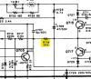
upload_2023-3-10_12-59-18.png

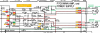
upload_2023-3-10_13-0-25.png

Map of new measured voltages.
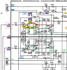
upload_2023-3-10_15-31-57.png
 
Last edited:
Sorry. You're right. I went back to my notes with readings from today. It is a 33k ohm as measured; I guess I fumble fingered that one. I'll get the Q703 measurement tomorrow morning. Any of these newly posted readings making any sense?
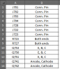
 
Any of these newly posted readings making any sense?
No... they don't. Please check the traces on the back side of the board for any trace cracks or cold solder joints, otherwise we will need to keep measuring voltages.
What transistor did you use as a replacement for Q701 and Q703?
Are they the same as Q702 & Q704?

Thanks. Tomorrow, can you measure the voltages below. We will start with the board interfaces.
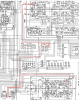
upload_2023-3-10_17-0-38.png
 
Last edited:
Just got back in. Here are the energized readings with R719 lifted:

Q703

E -38.61 VDC

C -38.57 VDC

B -29.42 VDC

Q701 readings were all -38.xx VDC.

I think it's best to reiterate an important factor. Initially, I had removed all of the components mounted to the back of this board. I had to use photos to try and restore things. In addition, two traces were damaged. I installed short jumpers to fix the issues. I have gone back and retraced my steps on this. I honestly believe I have them located correctly now, but initially I didn't, and this is when things were damaged and resistors were burning up.

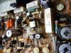
However, the two 1/4 watt 470 ohm resistors mounted to the back near the output transistors, I have serious doubts about. The reason is that my pics and your pics and other pics are different. Why are they there and could these be affecting the whole situation? I will take pictures of all of the back mounted components and where they are currently mounted, including jumpers. I should be able to get those posted very soon.
 
Pictures of the back of the board would be helpful to diagnose the problem. If you have a 'before' photo and 'after' photo that would also help.
Also, please list the value or the resistor or capacitor since sometimes you cannot read it in the photo.
I will compare them with my 2252B.
Also please take a photo of the board repairs that you made.
Did you remove any wires from the board before or did you leave them intact?
 
I took some pictures. I'll have to run them through the Paint program to reduce them etc. I thought it more important to get the readings.

The following were taken to Gnd, with R719 lifted and Q711 and Q713 removed.

J701 -33.41 VDC
J702 1.0 mVDC
J703 0.3 mVDC
J704 0.1 mVDC
J728 -0.3 mVDC
J722 35.2 VDC
J723 35.2 VDC

R723 36.22 VDC 35.24 VDC R727 35.24 VDC 13.24 VDC

Q753

E 14.4 VDC

C 38.87 VDC

B 15.02 VDC

Q750

E 35.25 VDC

C 46.0 VDC

B 35.83 VDC

Q751

E 15.0 VDC

C 35.82 VDC

B 15.6 VDC

After 15 mins of looking, I have not yet found Q741 or Q742. I will keep looking.
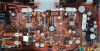
You had asked what I replaced Q701 thru Q704 with. I used KSA992FBUs.

Another important thing I noticed while energized. I routinely monitor components for heat. Today while I was taking the voltage readings, I noticed that R747 is running very hot. It wasn't smoking, but too hot to sit with your finger on it very long.
It shows as a 2.4 K ohm 1/4 w resistor. This is NOT one that I replaced. I read each side of R747 to Gnd. One side read 0.8 VDC, and the other side read 35.5 VDC. None of the other resistors around it felt abnormal.
 
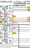
Here are your new voltage measurements on the schematic (shown in purple).
You have a large negative (-33.4v) voltage on J701, L channel. The R channel is 0v. It looks like a short on Q701 & Q703. The -38v collector voltage is appearing on both the emitter and base??
Could there be a short???

upload_2023-3-11_16-19-6.png

I also tried to trace down the wire path to J701.
upload_2023-3-11_16-18-14.png

One more thing to check... CE23 (also CE24) on PE01 (Tone Amp) board.
Did you put in a Non-polarized electrolytic capacitor??
upload_2023-3-11_16-42-40.png
 
Last edited:
These are the energized readings I just took:

Q741 Anode 38.63 VDC Cathode 38.64 VDC

Q742 Anode 307.0 mVDC Cathode -1.317 VDC

This is where the two 470 ohm 1/4w resistors are. One across Q741 and the other across Q742.
I'm headed back out to check CE23 and CE24 on PE01. Something tells me I didn't replace these, but I will find out shortly.
 
Last edited:
Q742 Anode 307.0 VDC Cathode -1.317 VDC
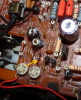
Did you mean 30.70VDC or 3.07VDC?

What's unusual is that all of the voltages that you measured are about the same (35v - 38v) for the one channel?? Where are you putting the black lead (-) of your meter when you take the readings, on the chassis (for all of the readings) or on the board somewhere (e.g. ground pin)?

Did you figure out how to attach a photo of the back side of the board (and front). I just use Windows "Snip & Sketch" to capture a screen image of the photo that I have displayed on my screen. Then just copy and paste. Good enough for most things.

Can you also check to make sure there is not a short between R716 and diode Q720 leads.
upload_2023-3-13_1-8-27.png
 
Last edited:
Well, it looks like I can't type either. The Q742 anode reading is 307.0 mVDC. I edited my previous post to show it.
All of the readings I've been taking, have been to chassis ground. I clip the negative meter lead to the metal chassis.

I checked CE23 and CE24 on PE01. Yes, I had replaced them with polarized caps. Something I don't ever remember doing on any receiver before this.
Usually, I leave them alone or replace them with a film cap. Apparently, I've made every mistake possible on this poor receiver. I dug out the original non-polar caps and tested them. They tested fine, so I put them back in.
I will continue to try to post pictures.
 
Here are some pictures. Some look very similar to each other as I tried to get good pics in focus.

2252B-2.jpg

2252B-3.jpg

2252B-2.jpg
 

Attachments

  • 2252B-4.jpg
    2252B-4.jpg
    140.1 KB · Views: 5
Well, I believe I have good news. After checking for a short between Q720 and R716. There's not one. I checked each end of R716 to each available spot on Q720. The lowest resistance read was 2.885 Kohms.

The good news is that I energized the unit for the first time since swapping the CE23 and CE24 caps back to original. Two seconds after I gave it power, the protection relay clicked in. Now I'd like to restore R719, and see if I can get things adjusted into spec. Do you agree? It was my inattention to detail that has caused all of the problems so far.
 
First, a couple of sanity checks to see if it fixed the issues:
  1. Check voltage at input J701 and J702.
  2. Check EBC of Q701, Q703 Q715, & Q717.
  3. Check diode Q741.
  4. Check EBC of Q711 and Q713 at socket.
If all looks well, the try to adjust offsets.
 
That elation was short lived. I restored R719. I reinstalled Q711 and Q713. I again energized, and the PR closed. I turned it off. I hooked up to set the amplifier voltages. I turned it on and this time the PR did not go closed. I measured across R 763 and R765. I read 18.4 mVDC. R731 had no effect at all. I went to the other side, and using R732, I adjusted it to 24mVDC.

At this point I stopped and turned it off. I looked and felt for signs of heat. Once again, C705 is starting to bulge on top and was very warm.
 
OK, let's start from the input to the bad channel and work our way through to isolate the issue.

upload_2023-3-14_7-42-4.png

Here's what to do:
  1. Remove or lift 1 leg of R701.
  2. Turn power on briefly and measure voltage at J701 to see if you still have -33V.
  3. Measure voltage on C701, 3.3uF cap. (EDIT)
  4. Measure capacitance of C701 (should be able to do it in circuit since only one leg is not connected to R701 anymore.
  5. I initially misread the value of C702/C702. From the schematic I thought it was 33uF, but looking at the parts list it is 3.3uF. Please check your cap values.
  6. Measure voltage of Q701 (EBC).
  7. Check C727 Mica Capacitor s/b 0.1uF/200V. Measure it for open please.
Post these measurements then we can proceed.

One more thing: You replaced Q705 and Q706 with KSC2383, but when I looked at the datasheets they are in a TO-92L package. Your photo shows a different type of package, looks like a TO-126? What brand did you use?
upload_2023-3-14_19-53-0.png
Here you say you replaced Q705 with a KSC26190?? Which is it?
upload_2023-3-14_19-57-23.png

Please verify the pinouts of whatever you used are ECB.
upload_2023-3-14_19-8-8.png
KSC2690 datasheet. This looks like what you have in the photo???
upload_2023-3-14_19-59-0.png
 
Last edited:
There appears to be an error in the schematic of the 2252B, P700 Main Amp and Power Supply board.
Schematic R726, 0.1 Ohm/200W should be R762, 10 Ohm/2W the same as R761 for the other channel as listed in the parts list.
R726 is listed as a 4.7K 1/4W resistor in the parts list. I don't recall this being in the list of errors.

upload_2023-3-14_22-18-45.png

One more thing... can you please take a photograph of the 4 power transistor tops located in the heat sink so that I can read the transistor numbers. Thanks.
 
Last edited:
We've got a little snow storm going on here, and it took out our internet and phone. Just got it back.
I removed Q711 and Q713. R719 is back soldered in place. I energized it and monitored C705 carefully. While I took the following readings, it didn't get hot.
I wanted to get these readings posted. I'll get back to the suggested testing.

Voltage to chassis Gnd: J701 -31.16 VDC J702 0.4 mVDC

Diode Q741 Anode 37.18 VDC Cathode 37.18 VDC

Q711 (socket)

E 36.75 VDC

C 37.56 VDC

B 36.75 VDC

Q713 (socket)

E 36.74 VDC

C -37.61 VDC

B 36.76 VDC

Q701

E - 36.54 VDC

C -36.56 VDC

B -36.54 VDC

Q703

E - 36.51 VDC

C -36.51 VDC

B -26.86 VDC

Q715

E 36.84 VDC

C 36.79 VDC

B -33.96 VDC

Q717

E 36.81 VDC

C 36.78 VDC

B 36.60 VDC
 
Last edited:
I don't understand your question regarding Q705. I stated that I replaced it with a KSC2690. That is correct. I don't see where I talk about a KSC26190. I don't even think there is such a transistor with that number. Please read my statement from before.
You said I replaced it with a KSC2383: " You replaced Q705 and Q706 with KSC2383, but when I looked at the datasheets they are in a TO-92L package." I cannot find any post where I said that. On the first page I stated:
" I found Q705 to be bad. I replaced the 2sc1885 with a KSC2690AYS. I also changed out Q706 the same way." I cannot find anywhere that I said I used anything but a KSC2690 for Q705 and Q706.
 
Back
Top Bottom