• Please note that Audiokarma will be offline briefly for updates early on Monday morning, September 28th.

2252B power/amp brd issues

I don't see where I talk about a KSC26190.
Sorry, fat fingers, I meant KSC2690. See below.

Again, here is your reference to KSC2690 for Q705 and Q706.
I cannot find anywhere that I said I used anything but a KSC2690 for Q705 and Q706.
upload_2023-3-15_10-6-36.png

and here is your reference to KSC2383 for Q705 and Q706.
You said I replaced it with a KSC2383: " You replaced Q705 and Q706 with KSC2383, but when I looked at the datasheets they are in a TO-92L package." I cannot find any post where I said that.
upload_2023-3-15_10-5-33.png
All you need to do is search your own thread to find these using Q705 or Q706 for the search terms. Maybe you need to seek technical service help in solving your issue. I'm only trying to lead you to a conclusion of the problem, but it's hard to diagnose when you make component parts errors and comments.

***Could you provide the voltage reading on both sides of R705 and emitters of Q701 & Q703 (again) please.***

One last thing. I have been keeping track of your measured voltages and on the last set you provided this AM the 'sign' of the voltage changed from the previous two measurements.
See below. Is that correct, or another error???
upload_2023-3-15_10-17-8.png
 
Last edited:
Here's what I have done:

I have verified that C701 and C702 are both 3.3 uF @ 50V Nichicon. The problem here is that as I went through the rebuild, I had been referring to a posting of parts etc. When it came to this pwr/amp board, he made a special point in saying that the polarity silk screen markings are incorrect, and that the polarity should be opposite when you replace it.

Following this guidance, I reversed C701 to opposite the silk screen markings. That was several weeks back. But now, I'm wondering if that is correct. Shouldn't the incoming signal come into the positive terminal of C701; exactly as it's shown on the schematic and the board layout drawing (pg 12 in the SM). Are you familiar with this issue?

I did the testing you laid out as best I could considering this C701 polarity issue. When I took the readings below, please be aware that C701 was installed in a polarity opposite that shown on the silk screen and schematic (i.e. capacitor neg to R701 leg).

Q711 and Q713 are still removed. R701 has one leg lifted (where it should connect to the + side of C701 per the sch.).

Powered on and measured J701 to chassis Gnd. After approx. 20 sec, the voltage stabilized at 0.0 VDC. Also occurring 2 secs after energizing, the protection relay snapped closed and stayed closed.

The (ECB) for Q701:

E -39.30 VDC

C -39.32 VDC

B -39.33 VDC

Right now C701 is pulled. I'd just like a pier check here. Thanks.
 
I read your concern regarding the Q705 and Q706 replacements. I know that what is installed on the board are KSC2690. I checked the numbers on the installed transistors visually. I verified that an adequate replacement for a 2SC1885 is a KSC2690. I referred to the current Marantz substitution list, and I have verified that their orientation is correct as installed on the board. I would really like to know the correct orientation for C701.
 
I would really like to know the correct orientation for C701.
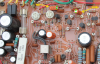
Here is a photo of my 2252B with factory caps, before I recapped. Yes, C701 marking of '+' is incorrect.
upload_2023-3-16_14-47-53.png

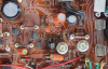
From the other direction, you can see the (-) on the cap.
upload_2023-3-16_14-51-20.png
 
Q711 and Q713 are still removed. R701 has one leg lifted (where it should connect to the + side of C701 per the sch.).
Powered on and measured J701 to chassis Gnd. After approx. 20 sec, the voltage stabilized at 0.0 VDC. Also occurring 2 secs after energizing, the protection relay snapped closed and stayed closed.
Good... so now we know that the -33V is NOT coming from the tone board, but localized to this board.
While you have R701 lifted, please measure the voltage on both legs of C701 and Q701 base to see if the negative voltage is still there.
I also would like you to check the voltage on both legs of R705, on the resistor leads (I want to see if there is an open between R705 to the emitters of Q701/Q702.)

You should be fine with R701 lifted for now, it's the large (-) voltage that I am concerned about.

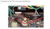
C701 is used to block DC from the amplifier and allow only AC signal in. Since in normal operation you probably have ~0VDC going into C701 and 0.03VDC at the base of Q701, technically the (+) should be on the 'more positive' lead, which is the base of Q701. The problem that we face now is that for whatever reason you have -33V on the (+) side of C701!

Thanks, we are getting there!
:)

upload_2023-3-16_15-11-13.png
 
Last edited:
I installed a new C701 and with the polarity opposite of the silkscreen markings. This was the way I had the previous one oriented. So the conditions of this test were Q711 pulled, Q713 pulled, C701 restored, and R701 with one leg lifted.

C701 -39.19 VDC (on the lead that normally links directly to R701 lifted leg)
-37.21 VDC (other lead)

Q701 BASE lead -39.30 VDC

R705 13.19 VDC on one side
-39.15 VDC on the other side
 
OK, good. Can you now measure and report the following:
  1. The emitter voltage of the emitter of Q701 (to ground) and the emitter voltage of Q702 (to ground) measured at the transistor lead (not the pad).
  2. Now, with power off and measure the continuity of the -39.15V side of R705 to Q701 emitter.
  3. Next, measure the continuity of the -39.15V side of R705 to Q702 emitter.
  4. Also, could you check for a short between the emitter and collector of Q701 & Q702.
Thanks.
 
Last edited:
Will do in the AM. Thanks for the continued help. It's not difficult to read ECB on either Q701 or Q702 right at the transistor legs.
 
Thanks. Could you also look at the back side of the board around the area of R705, Q701, Q702 for a solder bridge or cold solder joint or cracked trace. Somehow the positive voltage on R705 is not getting to the transistors or the transistors have a short between emitter and collector, passing the -40V?
 
I have some test data here. I'm not quite sure why you wanted to check Q702.

Powered test
Q701 Emitter to chassis Gnd voltage -38.45 VDC Q702 Emitter to chassis Gnd voltage 0.632 VDC

Powered down continuity readings

The following resistance readings were taken to the -39.15 VDC side of R705:
Q701 Emitter to R705 0.1 ohm
Q702 Emitter to R705 9.55 K ohms
Q703 Emitter to R705 0.1 ohm

The following readings were taken in situ (de-energized):
Q701 Emitter to Collector resistance 162.6 ohms
Q702 Emitter to Collector resistance 35.67 K ohms ohms
Q703 Emitter to Collector resistance 1.0 ohm

I also checked the back of the board and found no evidence of shorting. It agrees with the traces and schematic.
 
Last edited:
Thanks for being so patient, but we are on the right track.
  • Since the lead from R705 to Q701 and R705 to Q703 are the same = 0.1ohms, the path from resistor to emitters are both good.
  • Q701(e) to Q701(c) = 162ohms
  • Q703(e) to Q703(c) = 1ohm, looks like a possible short, but...
  • What I forgot to ask was to check these resistances with the DMM probes in both directions, that is one reading with (-) on emitter and (+) on collector, then reverse to (+) on emitter and (-) on collector (and note which direction). This will test the junctions.
  • We can also confirm the Q701 and Q703 (e) to (c) resistance measurements by measuring Q702 and Q704 measurements of the good channel for comparison.
  • Also, please check resistance of Q705 emitter to collector in both directions.
  • Sorry about the Q702 readings, my error, (must have been a late night) but it confirms that it is still good.
To summarize:
  • No open trace or cold solder on Q701 and Q703 to R705 connection
  • There is a difference in the Q701 and Q703 emitter to collector resistance
  • Maybe if Q703 has an (e) to (c) short, then the -38V on the collector is being conducted to the emitter also and since the emitters of Q703 & Q701 are connected you have -38V on the emitter also. Q701, when powered on, the emitter to base junction is forward biased so it will conduct the -38V to the base.
 
Last edited:
I'll do that testing this AM. When I measured Q703 e to c, I thought it strange. My meter always indicates 0.0 or 0.1 ohm when measuring a short. My meter was reading was an unwavering 1.0 ohm. I'm not sure there is a short. I will also measure in both directions when measuring resistances on the transistors again.
 
I believe we may have made a little break through here. While taking all of the de-energized resistance readings, the 1.0 ohm reading (e to c) on Q701, and the 162.7 ohm reading (e to c) on Q703 bothered me as compared to resistances in K ohms on the other channel. You know what difficulty it is to get to that portion of the board, so I decided to pull Q703. I measured it with my DCA55, and it showed a short (e to c). I had initially replaced Q701, 702, 703 ,and 704 (2SA750) with KSA992FBU. The reason I did that was because on initial inspection I saw definite signs of heating on the board silk screen around Q701 and Q703. I then pulled Q701 and it tested with a short between E and B.

I replaced both Q701 and Q703 with new KSA992FBUs. The readings on them now are:

Q701 E to C 12.10 K ohms (both probe orientations)

Q703 E to C 114.0 K ohms (both probe orientations)

The E to C resistance readings on Q702, Q704, and Q705 were 10.75 K ohms, 9.83 K ohms, and 5.88 K ohms respectively.

I stopped here as I would believe some powered testing is in order. Also, what about R701?
 
Hmmm....?
The circuits for the L & R channel are the same so I would expect to see the same resistance values for the odd and even transistor parts.
But we have:
Q701 (e) to (c) = 15K ohms (different from Q702)
Q702 (e) to (c) = 9.8K ohms (reference)
Q703 (e) to (c) = 114K ohms (different from Q704)
Q704 (e) to (c) = 9.8K ohms (reference)​
Need to find out why the difference between channels and get them close to the same.
Can you check Q705 and Q706 base to emitter and base to collector resistance and compare.

The emitter of Q703 and the emitter of Q704 should be connected to the same points:
C729, 22uF - should measure 0 ohms to Q703 (c) and 0 ohms to Q704 (c)
R721, 33 ohm - one side should measure 0 ohms to Q703 (c) and Q704 (c)
R722, 33 ohm - one side should measure 0 ohms to Q704 (c) and Q704 (c)
R713, 10K ohm - one side should measure 0 ohms to Q703 (c)
R714, 10K ohm - one side should measure 0 ohms to Q704 (c)​

Maybe try to compare the resistance measurements from these devices to chassis ground and see if you can find where the difference is.
 
Last edited:
Maybe my readings are misleading. These (e) to (c) readings are with the transistors installed. No line power, but I believe that every electrolytic cap can hold a charge. Yes, I discharge the main filter caps through a resistor. The point I'm making is that most of the readings I took today were quick ball-park readings. When I took these readings they drifted all over the place. I believe this very well might be because there is spurious voltage. I really wanted to see if replacing Q701 and Q703 made a big difference. I wasn't aware that measuring resistances was a way to match transistors. At any rate I have the original 2SA750 transistors and if necessary, I could put them back in.
 
It's just odd that on the 'good' channel, both measurements are the same and for the bad channel they are not only different but quite a bit different, and different from the 'good' channel.
For the other measurements, you are essentially measuring continuity of a circuit board trace, and all are connected, so it should read 0 ohms (or close to it) unless there is a break in the trace, a bad solder joint, or a solder bridge to another component.
 
Okay, I have some test results that look pretty darn good, I think. I want to reiterate that when I took the first set of readings, I was looking for a quick confirmation that the new Q701 and Q703 that I had just installed, didn't show any shorts. I also find that resistance readings are tricky on installed components do to changing readings between two points. I believe this occurs because one or more electrolytic caps in the circuit try to charge themselves from my DMM battery. I took most of these readings with a stabilization period of at least 1 minute, using my DMM with spring hook leads. I am absolutely certain that these resistances are accurate. They look a lot better to me.

Q701 (e) to (c) 14.10 K ohms

Q703 (e) to (c) 14.66 K ohms

Q702 (e) to (c) 14.22 K ohms

Q701 (e) to (c) 14.10 K ohms

Q703(e) to Q704(e) 13.74K ohms

Q705(b) to (e) 1.04 K ohms

Q705(b) to (c) 15.10 K ohms

Q706(b) to (e) 1.04 K ohms

Q705(b) to (c) 16.70 K ohms

All of the following read 0.0 ohm

C729, R721, and R722: All of them read 0.0 ohms to Q703(c), as well as Q704(c)

R713 to Q703 (c): 0.0 ohm

R714 to Q704 (c): 0.0 ohm
 
Very good. :) I think we are getting somewhere now!
Just a couple more things to check. With power-off, measure the resistance across Q741 and Q742 (diodes located on heat sink). I want to make sure that those are still good.
In one direction it should conduct, in the other direction it should be high impedance. Or if you have a diode check mode on your DMM you can use that.
Basically, what we are looking for is conducting in one direction, open in the other direction.
If this works, we then need to find out if any other components got damaged as a result of the high (-) voltages.
Do you still have the power transistors out?
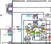
(For reference)
upload_2023-3-20_13-50-8.png
 
Back
Top Bottom