

You are using an out of date browser. It may not display this or other websites correctly.
You should upgrade or use an alternative browser.
You should upgrade or use an alternative browser.
2252B power/amp brd issues
- Thread starter mgl99
- Start date
-
- Tags
- 2252b power supply issues
I'm back on the resistor readings as of early this morning. I just broke for lunch, but I want to make sure we are comparing apples with apples, if you know what I mean.
I just wanted to know how you took your readings when you did, other than discharging the filter caps and grounding each resistor lead prior to taking the reading.
The reason I ask this question is linked to my observation previously; that electrolytic caps in line with the lead you are testing cause almost immediate changing of the reading.
Typically, it takes around two (or more) minutes to get a stable reading. Sometimes the reading starts high in the Meg ohms, and then decreases fairly rapidly into the K ohms and then finally stabilizes.
Other readings, start out low as soon as you touch the probe to the lead being measured (all were tested to chassis Gnd). A reading like 4.5 K ohms is typical. However, after about 2 mins., it stabilizes at
16.4 K ohms (for example). That's why I'm asking how you took the readings.
I just wanted to know how you took your readings when you did, other than discharging the filter caps and grounding each resistor lead prior to taking the reading.
The reason I ask this question is linked to my observation previously; that electrolytic caps in line with the lead you are testing cause almost immediate changing of the reading.
Typically, it takes around two (or more) minutes to get a stable reading. Sometimes the reading starts high in the Meg ohms, and then decreases fairly rapidly into the K ohms and then finally stabilizes.
Other readings, start out low as soon as you touch the probe to the lead being measured (all were tested to chassis Gnd). A reading like 4.5 K ohms is typical. However, after about 2 mins., it stabilizes at
16.4 K ohms (for example). That's why I'm asking how you took the readings.

Here are the steps that I took:
- All reading are taken with it unplugged.
- I have a little test lead with test hooks on both ends of a wire connected to a 1K ohm/5W resistor. I think you can use a 100ohm also, but that's what I had.
- Discharge main PS filter caps (with a 1K ohm resistor across the power supply terminals going to the Power Supply/Main board) across terminals J707 to J706 (GND) then J708 to J706 (GND).
- On the resistor that I am going to take an ohm reading I use my 1K ohm resistor (to GND) and touch it to the resistor lead (then take it off) just before I take my ohm reading.
- The black wire of my multimeter is connected to chassis ground and I measure with the red lead.
- If I do this, then most of the time I only need to wait for no more than 15-30 seconds for the reading to stabilize.
- Then, I do the other side of the resistor... same thing (sometimes you can get away with not discharging anything).
- Most of the reading seem to be about the same. I think it is because of the large cap on the 38V power line.
- I don't know if this will find anything, but what I was hoping to find by this easy test was to see if any of the ends of the resistors had a low resistance to ground... indicating a short.
I did take some readings in the other channel. Since R721, R728, and Q705 were previously damaged, I've started focusing on those. Though I replaced them, the condition more than likely is still there. Please take note of the readings I took on R721. You have 574 ohms on one side and 78K ohms on the other side. I have 862 ohms on one side and 831 ohms on the other. R721 is a 33 ohm resistor. There is quite a difference between 831 ohms and 78K ohms. There are also readings for R764 and R762, which are roughly 2K ohms higher than R763 and R765.
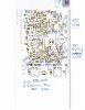
I re-measured R721 and got 574ohms and 549ohms (vs 78K). Must not have grounded lead before reading.Please take note of the readings I took on R721.
I measured R728 and got 548ohms (side closest to C729) and 527ohms.
I measured R762 and got 5.5K on both sides. (or did you really mean R766??)There are also readings for R764 and R762, which are roughly 2K ohms higher than R763 and R765
I measured R764 and got 5.5K on both sides.
You're right, it is R766 and R764 that I tested. I just came in for lunch, and I have some info. I'm glad to hear that your reading on R721 is really what it is. I am continuing to pursue R721, R728, and Q705 failures. Something over loaded in that circuit.
Review of the schematic is pushing me in the direction of investigating Q735 and possible effects to Q741. Q735 and Q736 identify as Varistors, Type STD-04. The Marantz substitution list doesn't identify a replacement. I left them alone. They're original.
I'm going to get readings on them to compare the two channels. I'll also be testing the resistors around Q735.
Review of the schematic is pushing me in the direction of investigating Q735 and possible effects to Q741. Q735 and Q736 identify as Varistors, Type STD-04. The Marantz substitution list doesn't identify a replacement. I left them alone. They're original.
I'm going to get readings on them to compare the two channels. I'll also be testing the resistors around Q735.
I tested Q735 and Q741. I had to lift one side of each in order to test them. Q741 tests as a good diode (DCA55). Q735 is a varistor and tests as a resistor. It tests good. I have been testing all of the resistors around Q735.
So far I have found nothing that jumps out at me. I will continue to test everything I can. I noticed that you did not test R728 in your unit. Since this is a resistor that had burned up, I would like to compare the readings I got, to yours.
R728 reads very similar to resistances seen on R721. My data is out in my shop. I will be posting again today with updated resistance readings. I also, pulled Q711 and Q713 and tested them (DCA55), and they continue to test as good. I put them back in.
Once again, I do sincerely appreciate your help.
So far I have found nothing that jumps out at me. I will continue to test everything I can. I noticed that you did not test R728 in your unit. Since this is a resistor that had burned up, I would like to compare the readings I got, to yours.
R728 reads very similar to resistances seen on R721. My data is out in my shop. I will be posting again today with updated resistance readings. I also, pulled Q711 and Q713 and tested them (DCA55), and they continue to test as good. I put them back in.
Once again, I do sincerely appreciate your help.
That's what I have been thinking. I'll go ahead and post my readings so far. I have been studying the schematic. Because R721, R728, and Q705 took damage last time under power, I'm going point-to-point starting with these components.
I believe that these components along with Q701 and Q703. I believe that everything "downstream" is being affected because it appears that -38.0 VDC, where I should have 0.6 VDC, at the emitters of Q701 and Q703. If you had to take a guess, where do you think this -38 VDC is coming from?
Transistor readings are to chassis GND.
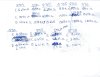

I believe that these components along with Q701 and Q703. I believe that everything "downstream" is being affected because it appears that -38.0 VDC, where I should have 0.6 VDC, at the emitters of Q701 and Q703. If you had to take a guess, where do you think this -38 VDC is coming from?
Transistor readings are to chassis GND.
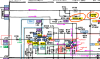
From these latest measurements above, the two resistors that stand out as' way-off' are R725 and R729. I'll recheck my readings (I got a different reading than before). Could you please take a look around these resistors for anything odd them read the ohms across the resistor. I would look at R725 since I got 17K and you got 5.4K. Thanks. Maybe we can get a clue.

Last edited:
I read your last post above. However, yesterday I decided to try some energized readings. I only kept it energized long enough to take these readings. They were all taken to chassis GND. Maybe these readings can shed some light.
Q701
E 17.56 VDC
C 17.56 VDC
B 16.87 VDC
Q702
E -36.04 VDC
C -39.7 VDC VDC
B 47.5 mVDC
Q715
E 39.6 VDC
C 39.6 VDC
B 36.6 VDC
Nothing appeared to be running warm. If we compare Q701 and Q702 voltages, there still appears to be be a mismatch between channels. I have been actively looking at R729 and R725, but I'll look at them again today. The PR did go closed.
By the way, R701 is no longer lifted, and wasn't lifted when I took the readings above.
Q701
E 17.56 VDC
C 17.56 VDC
B 16.87 VDC
Q702
E -36.04 VDC
C -39.7 VDC VDC
B 47.5 mVDC
Q715
E 39.6 VDC
C 39.6 VDC
B 36.6 VDC
Nothing appeared to be running warm. If we compare Q701 and Q702 voltages, there still appears to be be a mismatch between channels. I have been actively looking at R729 and R725, but I'll look at them again today. The PR did go closed.
By the way, R701 is no longer lifted, and wasn't lifted when I took the readings above.
If anything, you are worse off now than before because the R channel voltages are now bad (they were good before).
If you are serious about fixing this board, you need to quit applying power until you resolve the component or board issues, else you will be damaging more of the board.
Q701
E 17.56 VDC (was -38.4V... should be 0.6V)
C 17.56 VDC (was -38V... got worse)
B 16.87 VDC (was -36.5V... should be 0V)
Q702
E -36.04 VDC (was 0.63V... got worse)
C -39.7 VDC VDC (was -37.4V)
B 47.5 mVDC (was 0.04V)
Q715
E 39.6 VDC (was 36.8V... should be 0V)
C 39.6 VDC (was 38.2V... should be 1.1V)
B 36.6 VDC (was -33.9V... should be 0V)
R725 & R729 are only a clue to what may be going on. You did not provide more resistance measurements like I asked you to, so it's hard for me to do any diagnosis without your data. I have my 2252B open on my bench now so if you provide resistance measurements of the resistors, I can verify.
If you are serious about fixing this board, you need to quit applying power until you resolve the component or board issues, else you will be damaging more of the board.
Q701
E 17.56 VDC (was -38.4V... should be 0.6V)
C 17.56 VDC (was -38V... got worse)
B 16.87 VDC (was -36.5V... should be 0V)
Q702
E -36.04 VDC (was 0.63V... got worse)
C -39.7 VDC VDC (was -37.4V)
B 47.5 mVDC (was 0.04V)
Q715
E 39.6 VDC (was 36.8V... should be 0V)
C 39.6 VDC (was 38.2V... should be 1.1V)
B 36.6 VDC (was -33.9V... should be 0V)
R725 & R729 are only a clue to what may be going on. You did not provide more resistance measurements like I asked you to, so it's hard for me to do any diagnosis without your data. I have my 2252B open on my bench now so if you provide resistance measurements of the resistors, I can verify.
Last edited:
You're right, I am worse off. I won't do any more energized testing. I didn't think we were making progress, because my readings and your resistance readings aren't meshing. That is, my readings drift for longer than 15 secs. I've tried grounding the resistor for test, and then immediately take the reading. What starts at 5.9 Meg ohms, may well end up at something like 16.2 K ohms. How am I to measure the value accurately?
Anyway, I'm not going to give up. I'm going back out and I will (again) scrutinize R729 and R725 and surroundings. What would have caused the changes from -38 VDC readings on the transistors, to +17 VDC? I was hoping that those powered readings I just took weren't in vain.
Anyway, I'm not going to give up. I'm going back out and I will (again) scrutinize R729 and R725 and surroundings. What would have caused the changes from -38 VDC readings on the transistors, to +17 VDC? I was hoping that those powered readings I just took weren't in vain.
This is my mid-day report. This is exactly what I have been talking about. These are resistance test numbers for the following. I will upload the updated drawing this evening, but for now, I want you to see these numbers first.
These were taken very carefully after discharging the filter caps (again) and grounding each resistor lead to chassis ground just before testing resistance to chassis GND.
I want to emphasize that these readings were aloud to completely settle out before they were taken: (referenced to the location drawing)
R725
Lead closest to Q721 10.13K
Lead farthest from Q721 13.84K
R729
Lead closest to Q735 7.1K
Lead farthest from Q735 15.92K
R713
Lead closest to C707 738 ohms
Lead farthest from Q721 7.0K
R714 (for comparison to R713)
734 ohms
6.9K
I was wondering if you could try something. To perform this test you should use a mini-grabber on the DMM positive test lead. Pick one of the resistors, and a specific lead to test. Do the grounding thing. With DMM neg lead to chassis GND,clip the positive mini-grabber to the lead you picked and immediately write down the resistance reading you got. Note the time, and then wait at least 4 minutes to read the DMM again. Is there a difference? Please let me know. Also, please note in the readings I just posted, that R714, which is in the operating channel, pretty much matches R713 resistance readings. However, they are both grossly different than the readings you posted from your unit. Last time this happened (on R721), you took readings again, and came up with something far different.
Well, back on it!
These were taken very carefully after discharging the filter caps (again) and grounding each resistor lead to chassis ground just before testing resistance to chassis GND.
I want to emphasize that these readings were aloud to completely settle out before they were taken: (referenced to the location drawing)
R725
Lead closest to Q721 10.13K
Lead farthest from Q721 13.84K
R729
Lead closest to Q735 7.1K
Lead farthest from Q735 15.92K
R713
Lead closest to C707 738 ohms
Lead farthest from Q721 7.0K
R714 (for comparison to R713)
734 ohms
6.9K
I was wondering if you could try something. To perform this test you should use a mini-grabber on the DMM positive test lead. Pick one of the resistors, and a specific lead to test. Do the grounding thing. With DMM neg lead to chassis GND,clip the positive mini-grabber to the lead you picked and immediately write down the resistance reading you got. Note the time, and then wait at least 4 minutes to read the DMM again. Is there a difference? Please let me know. Also, please note in the readings I just posted, that R714, which is in the operating channel, pretty much matches R713 resistance readings. However, they are both grossly different than the readings you posted from your unit. Last time this happened (on R721), you took readings again, and came up with something far different.
Well, back on it!
*** I need to retake these readings. I was getting different readings with my 3 meters (Fluke 117, Fluke 87V, and Agilent 34401A). If I ground the red lead while hooked up to the resistor the readings are mostly the same. ***
Here are my readings compared to yours. (Discharged caps yesterday, grounded out both sides of the resistor under test with 1K resistor to chassis ground, waited 4min unless reading was stable sooner.
Measurements were taken with my Agilent 34401A 6-1/2 digit multimeter.
I'm not sure why the difference since last time? May be afffected by the large cap to ground, C729?
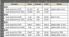
Here are my readings compared to yours. (Discharged caps yesterday, grounded out both sides of the resistor under test with 1K resistor to chassis ground, waited 4min unless reading was stable sooner.
Measurements were taken with my Agilent 34401A 6-1/2 digit multimeter.
I'm not sure why the difference since last time? May be afffected by the large cap to ground, C729?
Last edited:
I had some trouble getting stable, repeatable resistance readings. I tried 3 different DMMs and they varied a bit in measurements. Even going back to measure caused some differnces... maybe because of the large cap.
I also took some powered-on voltage readings (in ovals), but we'll save that for later.
On post #149 you made resistance measurements to GND for ECB of Q707,Q 709, Q708, Q710. I measured mine and got some different values.
We haven' done much testing on these. Can you see if these transistors are bad? My thinking is that if they are shorted, they can pass the large collector voltage to the emitter or base.

I also took some powered-on voltage readings (in ovals), but we'll save that for later.
On post #149 you made resistance measurements to GND for ECB of Q707,Q 709, Q708, Q710. I measured mine and got some different values.
We haven' done much testing on these. Can you see if these transistors are bad? My thinking is that if they are shorted, they can pass the large collector voltage to the emitter or base.
I believe I may found the missing link between your readings and mine. Please try this: Get a jumper with alligators on both ends. Clip one end to chassis GND. Clip the other end to the filter cap terminal where the RED wires attach. This keeps the filter caps discharged. Why do I think this is it? Because I was in the progress of taking a resistance reading on one of the odd numbered resistors. It was doing it's normal drifting thing, and was reading about 16.86 K on it's way higher. I then attached the jumper as I described above. As soon as I did, the reading jumped to 5.4 K almost immediately. I then removed the jumper temporarily, and the reading jumped up and began to climb. I think this would give more stable readings, and really give us something to compare equally. My DMM is an IDEAL model 61-481. Let me know if my theory holds up.
What is the "J" number of the terminal post with the red wire that you want me to ground? Are you referring to J707?Clip the other end to the filter cap terminal where the RED wires attach.
I don't know the "J" number. I'll look it up, but I didn't think you would need it. I'm talking about the two 10000 uF filter caps. If you look at them, you see two heavy gauge red wires soldered to the positive lug of one cap. There is the metal jumper strip which goes from the negative lug of the first cap (with the red wires on the positive lug), to the positive lug of the second cap. Soldered to the negative lug of the second cap, are two heavy gauge white wires.
You clip one alligator clip of your temporary grounding jumper to the filter cap lug where the two red wires are soldered. Then clip the other end alligator to chassis ground. This effectively keeps the filter caps (both of them) grounded out. Then take resistance readings. Below is a picture you posted earlier in this thread. Just by coincidence, it happens to show exactly what I've been trying to tell you. This is where you clip the grounding jumper. I think it's pretty straight forward, but I will search for a "J" number for you.

You clip one alligator clip of your temporary grounding jumper to the filter cap lug where the two red wires are soldered. Then clip the other end alligator to chassis ground. This effectively keeps the filter caps (both of them) grounded out. Then take resistance readings. Below is a picture you posted earlier in this thread. Just by coincidence, it happens to show exactly what I've been trying to tell you. This is where you clip the grounding jumper. I think it's pretty straight forward, but I will search for a "J" number for you.