I'm in progress of going over all of the odd numbered R7** resistors again with the grounding jumper installed. I believe then we can compare apples and apples, if you know what I mean. Please let me know if this is working for you. I really believe we can get rid of a lot of the confusion this way, and we can focus on the readings that are different, and possibly identify the issues.


You are using an out of date browser. It may not display this or other websites correctly.
You should upgrade or use an alternative browser.
You should upgrade or use an alternative browser.
2252B power/amp brd issues
- Thread starter mgl99
- Start date
-
- Tags
- 2252b power supply issues

OK, I re-measured the ohms using my Agilent 84401A with the cap red lead grounded, as you said.
Before each reading, I grounded out the resistor leads using a 1K resistor before attaching the DMM leads.
Noted both an immediate reading then waited about 4 minutes to stabilize then took a 2nd reading.
Here they are compared with your readings and my previous readings.
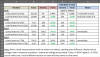
They pretty much match my previous readings except for R714 (I must have not discharged fully before).
I remeasured R714 with my other DMM and got different resistances which had me puzzled?
Then, I measured the DMM voltage used across leads to measure ohms, and here is what I found:
I wonder what voltage your Ideal 61-481 is?
Before each reading, I grounded out the resistor leads using a 1K resistor before attaching the DMM leads.
Noted both an immediate reading then waited about 4 minutes to stabilize then took a 2nd reading.
Here they are compared with your readings and my previous readings.
They pretty much match my previous readings except for R714 (I must have not discharged fully before).
I remeasured R714 with my other DMM and got different resistances which had me puzzled?
Then, I measured the DMM voltage used across leads to measure ohms, and here is what I found:
Agilent 84401A = 2.4V
Fluke 87V = 2.4V
Fluke 112 = 0.6V
That difference in voltage may bias some diode or transistor voltages to conduct and cause a different resistance reading.Fluke 87V = 2.4V
Fluke 112 = 0.6V
I wonder what voltage your Ideal 61-481 is?
Maybe it didn't make much of a difference in your readings, I get that. It makes a heck of a difference in my readings. Taking the readings with this jumper installed, makes me believe in the data I'm getting. A few readings still take maybe 45 secs to stabilize, but not 5 minutes! I believe if we both test with the temp grounding jumper installed, the defect will be identified. I never liked the drifting. As I have said in several posts, taking resistances is a great idea, as long as they are taken in a similarly controlled way. I'm not sure of my DMM test voltage, but I think that's a mute point. The variations in testing data were not being caused by a difference in DMM test voltage.
If you are convinced that all of the readings you took originally are not in need of being retested now that the jumper is in, I'll use that to compare to. If you do retest, I think you may find some surprises.
I am going to continue to take all new resistance data, because I don't trust my original data. I will post what I have tonight. As always, thanks for your help.
If you are convinced that all of the readings you took originally are not in need of being retested now that the jumper is in, I'll use that to compare to. If you do retest, I think you may find some surprises.
I am going to continue to take all new resistance data, because I don't trust my original data. I will post what I have tonight. As always, thanks for your help.
The measurements in the blue column above were taken with the jumper installed and with my Agilent DMM and they seem to be repeatable with the previous measurements.
I looked up the manual for your 61-482 and here is the spec for resistance measurements:

It looks like it uses 1.3V for resistance measurements. This is in between the 0.6V and 2.4V for my meters.
I looked up the manual for your 61-482 and here is the spec for resistance measurements:
It looks like it uses 1.3V for resistance measurements. This is in between the 0.6V and 2.4V for my meters.
Last edited:
OK.
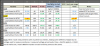
The measurement that stands out is R729 (lead closest to Q735). My reading is twice yours.
I would try to measure the resistors around that same area, then I can check mine. Probably also need to unsolder and check diode Q741.
- I grounded the red wire as before, also grounded (-) of C729 to prevent charging of cap.
- Set my DMM to manual scale to prevent switching scales and possible change in voltage used for resistance measurements.
- Re-measured 4 resistor values and compared to your readings.
- Now it looks like I can duplicate (close) your measurements.
The measurement that stands out is R729 (lead closest to Q735). My reading is twice yours.
I would try to measure the resistors around that same area, then I can check mine. Probably also need to unsolder and check diode Q741.
I think we're there as far as comparing measurements. What I have found is that some of my readings haven't changed from when I took them without the grounding jumper. However, many readings have changed greatly.
That's why I am going over all of the odd resistor readings, and I'm going to take some on the even side.
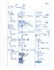
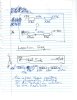
I am attaching pics of my notes. I know I don't get points for neatness, but I think you can read it. The obvious mismatch is between resistances to chassis GND of R763 and R765 as compared to R764 and R766. All of the readings
you see here, were taken with the grounding jumper installed. The resistances of R763 and 765 changed dramatically with the installation of the grounding jumper, however, the readings on R764 and R766 stayed the same after installing
the ground jumper. This would be something to look at immediately, do you agree?

That's why I am going over all of the odd resistor readings, and I'm going to take some on the even side.
I am attaching pics of my notes. I know I don't get points for neatness, but I think you can read it. The obvious mismatch is between resistances to chassis GND of R763 and R765 as compared to R764 and R766. All of the readings
you see here, were taken with the grounding jumper installed. The resistances of R763 and 765 changed dramatically with the installation of the grounding jumper, however, the readings on R764 and R766 stayed the same after installing
the ground jumper. This would be something to look at immediately, do you agree?
Yes, and you should probably check out R757/R759 and the other channel R764/R765 for comparison, it may provide a clue.
I'll try to check mine in a bit.
I like the up/down, left/right orientation pics. What side is toward the front of the receiver?
EDIT: Here are my readings for R763 / R765 and R766 / R764.
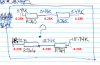
P.S. I get a ~20K reading if I do not ground the resistor lead prior to ohms measurement. I also tried removing my "extra" ground wire to R729 and it had no effect on the resistance readings.
I'll try to check mine in a bit.
I like the up/down, left/right orientation pics. What side is toward the front of the receiver?
EDIT: Here are my readings for R763 / R765 and R766 / R764.
P.S. I get a ~20K reading if I do not ground the resistor lead prior to ohms measurement. I also tried removing my "extra" ground wire to R729 and it had no effect on the resistance readings.
Last edited:
I'm not sure I understand your message. I have the readings for R764 and R765; they're on my drawing. I put the wire loops on the ends of R763 and R764 in my drawing. As you face the back of the heat sink, you can see how they're installed. Just look at the wire loops. If it's still confusing, I can redraw it.
Never mind, it's not worth explaining.I'm not sure I understand your message.
Well it appears that we have another mystery. Why are the readings so high on the "even" channel; the one that appears to be working? I'm just wondering what would drive up the resistance to that extent on R764 and R766. I am continuing to take resistor readings. I'm glad you are able to record these readings to see the big picture. I admit honestly, that I'm not good at all the computer stuff; I'm glad you are. It helps a lot to see the readings charted out on the location drawing or the schematic. More readings to come. Sure wish there was a way to research why I'm getting four times as much resistance on R764 and R766, than on R763 and R765.
I don't know if I can test them in place or not. I'll figure it out. I did find a bad trace between Q701 (c) and Q705 (e). Besides taking resistor readings to GND, I've also been reading resistance between transistor legs and chassis GND. That's how I found this open trace. I fixed that issue. I'll be putting more readings up today.
I wanted to post last night, but I was up late last night. I pulled Q707 and tested it (again) with the DCA55. It tests good. I had already pulled Q707 and Q709 once to test them. However, I did it again. I am not going to pull Q709 to test it again, since this board is taking a beating. The following pages are the readings. I still think I need to figure out why the resistance readings on R766 and R764 are so much higher than the other channel (R765 and R764).

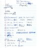
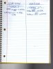
I was just going to suggest the same thing to you. Here are my mid-day readings. Temp jumper from filter caps installed. I ground every resistor lead just before testing. Even with the temp jumper installed, the other caps on the board
affect some readings. You already pointed this out, and I agree.
Is it possible that the EVEN channel, could be affecting the ODD channel? It seems that some EVEN channel components do have readings similar to your unit, however, there are many that far exceed those of your unit.
The odd numbered components seem to more equally match yours. Remember, when power ON took out R721, it also took out R728.
I want to keep take resistances until I can figure out what is causing the gross mismatch between the two channels in resistances.
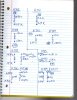
affect some readings. You already pointed this out, and I agree.
Is it possible that the EVEN channel, could be affecting the ODD channel? It seems that some EVEN channel components do have readings similar to your unit, however, there are many that far exceed those of your unit.
The odd numbered components seem to more equally match yours. Remember, when power ON took out R721, it also took out R728.
I want to keep take resistances until I can figure out what is causing the gross mismatch between the two channels in resistances.
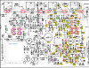
OK, I add a few more reading on here. Telling yours and mine apart was getting confusing so I labeled my readings with white text and colored background. Yours are just in colored text. Also Red is for the "odd" parts, magenta is for the "even" parts. So on the good side your/my readings are close, but on the bad side we differ in most.

Last edited:
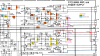
Did you change C727, the large 0.1uF/200V film cap? I've been trying to trace through the differing resistance measurements and voltages.
One other item, can you tell me the transistor part no. you have for each socket (J733, J734, J735, J736).
Thanks
One other item, can you tell me the transistor part no. you have for each socket (J733, J734, J735, J736).
Thanks
Last edited:
Back again. I was in the progress of verifying the following: J733 2SC1343, J734 2SA753, J735 2SA753, J736 2SC1343.
While I was verifying this information, I moved R763 to just verify the J number. I noticed that a heavy gauge orange insulated wire was just hanging in the air about 1/4 inch above the board.
This lead runs from aft of J736, where it is soldered into a hole in the board, marked "B" with an arrow. The lead runs right along the heat sink board junction. It only took a second to see where it belonged.
There is a hole between J734 and J733, also marked with a "B". This lead is a heavy gauge solid lead.
The solder joints were factory. I had no reason to undo them, and due to their run along the heat sink, you don't really notice it much. The solder joint had let loose, and on the back side
showed that there was NO wire end protruding through the solder joint. Inspection of the end of the lead, showed what appeared to be about 1mm of actual solder joint.
I remade this joint (correctly) and looked at the traces. Traces are fine; just a bad solder job at the factory.
I haven't started re-taking resistance readings, but I wanted you to know what I found. I haven't had the time yet, to sit down with the schematic and see what effect that lead being disconnected would have.
Back to the shop to find out.
While I was verifying this information, I moved R763 to just verify the J number. I noticed that a heavy gauge orange insulated wire was just hanging in the air about 1/4 inch above the board.
This lead runs from aft of J736, where it is soldered into a hole in the board, marked "B" with an arrow. The lead runs right along the heat sink board junction. It only took a second to see where it belonged.
There is a hole between J734 and J733, also marked with a "B". This lead is a heavy gauge solid lead.
The solder joints were factory. I had no reason to undo them, and due to their run along the heat sink, you don't really notice it much. The solder joint had let loose, and on the back side
showed that there was NO wire end protruding through the solder joint. Inspection of the end of the lead, showed what appeared to be about 1mm of actual solder joint.
I remade this joint (correctly) and looked at the traces. Traces are fine; just a bad solder job at the factory.
I haven't started re-taking resistance readings, but I wanted you to know what I found. I haven't had the time yet, to sit down with the schematic and see what effect that lead being disconnected would have.
Back to the shop to find out.
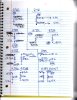
Last night I went to the shop and took a few various resistance readings to see what effect landing the heavy orange lead had on the readings. The information is a little hard to read, because it was getting late.
Basically what I noticed was that readings in the "even" channel that were previously reading around 18.8 K, are now reading right around 11.5 K. Readings in the "odd" channel that were around 5.2 K, are now reading around 4.3 K.
The few readings I took last night are here. I've noticed that your readings on R763, R764, R765, and R766 have changed drastically. They were around 5.4K, and now they're reading 20K?

Basically what I noticed was that readings in the "even" channel that were previously reading around 18.8 K, are now reading right around 11.5 K. Readings in the "odd" channel that were around 5.2 K, are now reading around 4.3 K.
The few readings I took last night are here. I've noticed that your readings on R763, R764, R765, and R766 have changed drastically. They were around 5.4K, and now they're reading 20K?