• The move to the new server is done. There are some software and database maintenance updates in process. This has us passing the hat around to help out. We appreciate any donations. Seriously, even a dollar helps. The payment page may be found here - https://www.audiokarma.org/support.html

2252B power/amp brd issues

  1. Verified polarity of Q709 collector. - Done
  2. Remove Q711. You don't need to unsolder Q711. You should be able to loosen the two screws that hold the transistor to the heat sink. You should be able to put a screwdriver through the access hole in the chassis to get to the screws. Unscrew them then gently pull the transistor out of the socket. Mark which transistor goes where with a marker. Try not to destroy the mica insulator.
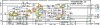
  3. upload_2023-3-2_12-6-21.png
  4. Test the transistor on your transistor tester.
  5. Measure voltages of Q711 at either the board traces or transistor socket lugs for EBC.
  6. Now, re-measure the voltages of Q715 & Q717 to see if the 38V is cleared.
That's it for now. Then we will see how to proceed after testing the transistor and reading voltages.
 
OK, fair warning, I think these B models don't have a discharge resistor on the negative filter cap so can emit a big spark when you least expect it. Use a power resistor of about 100 ohms plus and maybe 2 watts or more to discharge. I don't recommend using a screwdriver to directly snap them off to ground, the impulse can blow the FET(s) in the front end.
 
I am somewhat concerned about pulling the one output transistor (Q711) and energizing the unit. I have never done that before. I did pull Q711 and tested it with the DCA55 tester, (this is the third time I have done so). It tests good as it always has. I somewhat understand your concern regarding Q711 being shorted internally, but really, wouldn't that show up with the DCA 55 tester?? I think that is highly unlikely that this transistor is bad. All four of them have been tested and re-tested as GOOD.

I pulled Q715 and Q717. They both tested good. I re-installed them.

While I was inspecting the solder joints and the components themselves. As I said, initially I recapped all of the electrolytics on this board. What I found on visual inspection, was that C705 (47uF @ 50V), appeared visually swollen. Then I remembered that it was Q705 that I had found failed earlier on, and I surmise that whatever event took out Q705, may have taken C705 with it. I replaced it again, with a 47uF @ 63 VDC. I am starting to wonder if maybe diodes Q738 through Q740, and Q749 could be affecting things. They are all identified as WO6, which according to others, can be replaced with a 1N4004. I have not pulled them to test them.

I took ECB readings on Q713 at power. E 37.65 VDC C -38.48 VDC B 36.80 VDC

I have not re-energized the unit since replacing the C705. The current status is that I have the filter caps and bracket hanging, and the diode mounting plate as well. I feel a little squeamish about powering up with that arrangement. Last night I left them that way in case I had to pull something else to test.

 
A little time delay there with your posts. I ALWAYS use a discharge resistor to discharge the filter caps before attempting any work. You needn't worry on that aspect. But honestly, I can't imagine that Q711 would test good on the DCA55 tester with a dead short between any two legs. Please clarify what is next from this point.
 
OK, here's a summary of the above.
upload_2023-3-4_8-54-10.png

Where is Q749? I couldn't find it.
The bottom channel voltages look good, so we should concentrate on the 'odd' numbered part numbers (top channel).
Have you pulled Q713 and tested it on your DCA55, I don't recall?
You might be able to test diodes Q737 and Q739 with your DMM in circuit. Look for a short in the reverse bias direction.

The only other active devices to test in the top channel are:
Q713
Q707 & Q709.
Did you retest Q701, 703 and 705 after the smoke?
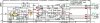
(Updated diagram attached)
 

Attachments

Good time to pull Q713 and test it. I can also Q707 and Q709. I did retest Q701, Q703, and Q705. However, I haven't tested anything under power since replacing C705. As far as Q713 is concerned, if you look above (on this page) at a previous recent post, you will see the answer to your question
 
If Q707 is shorted, it will pass the 39.4v to the base and emitter. This could be causing the high voltage on Q711 & Q713 bases.
 
Last edited:
Sorry in posting these results late today.

While inspecting the the board (again), and I recognized a swollen C705, 47uF @50 VDC. Since I had already recapped the board, I knew it wasn't an old one. Since I found Q705 damaged earlier, I had replaced it with a KSC2690. I believe this C705 damage may have been caused when the original Q705 got damaged. When I removed the damaged C705, I naturally checked the polarity before I unsoldered it. The polarity as installed was correct. I tested it with a meter, and it read 31uF. I installed a new 47uF @ 63 VDC.

I pulled Q715 and Q717 (individually) and tested them. They both tested as good. I reinstalled them.

You had asked where Q749 is located on the board. Q749 is very close to Q753 (which is attached to the heat sink).

I also wanted to let you know that Q701 through Q704 (2SA750s), early on I had replaced these with KSA992. The reason I had done this, is that the readings on the 2SA750s varied quite a bit with their respective hfe values. I matched up the (4) KSA992s with respect to very close hfe readings. I have since given you ECB energized readings on Q701 through Q704.

Once again, I just wanted you to know that I have not energized the unit yet. If there is more info needed from the bottom side, I still have the filter caps and bracket pulled back, as well as the diode heat sink.

These are the last ECBs taken on Q705 and Q706.

Q705 (KSC2690)

E -38.39 VDC

C 38.22 VDC

B -38.34 VDC


Q706 (KSC2690)

E -38.16 VDC

C -1.285 VDC

B -37.58 VDC
 
Thanks, close to what you had before. Your choice, but I would pull out Q711 and Q713 then measure the voltages at the transistor socket for both. You won't damage the board with these out, but you should have this on a dim bulb when you test in case there is a short somewhere. We are looking to see if the base voltage to both are 0.5 and -0.5v and that the emitter voltage is at 0v for both.
 
Here is what I have going in order to get all the readings you would like, and in a safe manner.

Q711 pulled & tested with DCA55. It tests good.
Q713 pulled & tested with DCA55. It tests good.

Q737 removed from brd. Tests good with DCA55. Reinstalled on brd
Q739 removed from brd. Tests good with DCA55. Reinstalled on brd
Q749 removed from brd. Tests good with DCA55. Reinstalled on brd

I had observed that the ECB for the Q711 and Q713 sockets are easily accessible from the topside of the board with each pin being label EC&B. Therefore, unless something else is needed, such as unsoldering other components to test, off the brd where access to area under the filter caps is needed, my next step is going to be to remount the filter caps bracket (only two screws needed for a safe mount during energized test). I will also remount the diode bracket.

Now it can be placed in it's normal position on the bench. I removed the topside heatsink screw mounted small plate, in order to pull and test Q737 and Q739. It also gives access to the test points described above. Q711 and Q713 will remain pulled during the energized test. Including easy access to J707 and J708 for readings to ground you had asked for, as well as access to smaller transistors for ECB voltages.

I will finish preps tomorrow, and plan to run the energized test. If there are any other energized readings you would like me to get, (in the test configuration with Q711 & Q713 pulled), please let me know.
 
I forget if you said before, but do you have a Dim Bulb Tester (DBT) to plug the receiver into?
If you can, please check the previous voltages I have highlighted in yellow to see if any changes.
But first, check the Q715 and Q717 emitter voltage. It should be 0, but was 38v before.
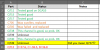
Screenshot 2023-03-06 170159.jpg
 
Last edited:
I do not have a Dim Bulb Tester, but I will get the readings the best I can. I've done pretty well through the years with good lighting and a steady hand. Hope to be posting results today, unless I energize it this morning and smoke appears. I sure hope not.
 
The purpose of a Dim Bulb Tester is so that you do not burn-out your equipment if there is a short circuit. It is basically an incandescent light bulb wired in series with an AC socket and switch. You plug your equipment into the DBT and the EBT into the wall socket. Turn-on your equipment and use the light switch to apply AC power. If all is good, the bulb will momentarily be bright then dim down to a gentle glow. If there is a short in your equipment, instead of it drawing infinite current from the wall socket, the bulb will glow brightly (since the equipment short looks like the bulb is connected to the AC) and all of the voltage drop will be across the bulb and not your stereo. You can build one yourself from parts from Home Depot. Look on the internet for wiring.
 
I'll do that, probably have the stuff here. Any particular wattage of bulb? Can't do it right now.
I was going to ask you this: If I energize and test the Q711 and Q713 sockets (ECB), and I find that the readings haven't changed, do I still need to test ALL of the other associated transistors in the channel as you specified in your previous post?
 
Last edited:
Any particular wattage of bulb?
Usually 60W to 100W incandescent bulb (NO LED or fluorescent bulb).
Let's start with looking at Q711 and Q713 socket voltages first, then check Q707/Q709 emitter voltages then decide the next step.
 
I didn't get to take the energized readings yesterday. I will get them first thing today. We had a family illness that needed to be addressed.
 
Okay, finally got some time. Here's what I found: I energized and let it warm up while I monitored it. No smoke, and after 20 mins I took the following readings (all readings to GRND).

Q711 (socket)

E 37.25 VDC

C 38.00 VDC

B 37.22 VDC


Q713 (socket)

E 37.19 VDC

C - 38.00 VDC

B 37.22 VDC


Q715

E 37.29 VDC

C 34.29 VDC

B 34.33 VDC

Q717

E 37.23 VDC

C 0.00 VDC

B 37.12 VDC

Q743

E 0.1 VDC

C 0.644 VDC

B 0.692 VDC


Q744

E 65.0 mVDC

C 37.91 VDC

B 11.00 mVDC


Q745

E 0.1 VDC

C 37.91 VDC

B 62.0 m VDC

There was no smoke or overheating of any kind. I stopped here. Hope this is helpful.
 
EDIT: Before you start doing that described below, could you please check C709 (47uF/50V) to make sure it is not shorted. If it is shorted, it could be passing 35V to the emitters of Q715 & Q717 instead of blocking DC and not allowing R711 to set to zero. If you have another, I would try replacing it anyway. Also, please make sure the polarity on the board is correct.
------------------------------------------------------------
Thanks. I would like to isolate where the large voltage (38v) is coming from.
Could you remove (one leg) of R719 33K then remeasure the same voltages as above (Q711, Q713, Q715, Q717 and Q709.
Also measure Q704 and Q704 again, thanks.

Screenshot 2023-03-08 175803.jpg

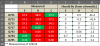
I put your measured voltages into a table for reference:
upload_2023-3-8_18-1-59.png
 
Last edited:
I pulled C709 after I verified that it had been installed in the correct polarity (as marked). It was new since I had already replaced it. I had a 47 uF @ 63 VDC installed and it showed no signs of failure and tested fine. I installed a new 47uF @ 63 VDC. After I installed the new one, I verified that polarities are correct per the schematic.
I lifted one end of R719. It read out at 33 ohms.

I then energized and took the following readings:

Q711 (socket)

E 38.21 VDC

C 38.98 VDC

B 38.18 VDC

Q713 (socket)

E 38.21 VDC

C -38.94 VDC

B 38.14 VDC

Q715

E 38.11 VDC

C 38.21 VDC

B 37.96 VDC


Q717

E 38.12 VDC

C 0.391 VDC

B 37.98 VDC

Q709

E 38.11 VDC

C -38.87 VDC

B 38.52 VDC

Q704

E 0.615 VDC

C -38.32 VDC

B 39.6 mVDC

I'll leave things configured as they are for now.
 
Back
Top Bottom