• The move to the new server is done. There are some software and database maintenance updates in process. This has us passing the hat around to help out. We appreciate any donations. Seriously, even a dollar helps. The payment page may be found here - https://www.audiokarma.org/support.html

6l6 mystery amp

Carbsandcaps

Super Member
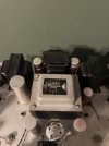
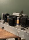
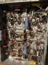
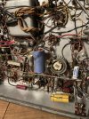
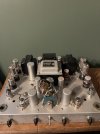
Just bought what appears to be a homemade 6l6 stereo amplifier. It uses 2 12ax7’s, 1 6sn7, and two 6l6gc’s on each side. Has selenium rectified preamp heaters, a big choke and a ton of capacitance. Has a bunch of controls that I haven’t been able to identify yet. It was supposedly made by a former RCA engineer (you know like every unknown amp is claimed to be). And it’s big! Does anyone recognize this amp? I want to restore it with some new capacitors ect. But I want to know what it is first.
 

Attachments

  • IMG_3672.jpeg
    IMG_3672.jpeg
    95.8 KB · Views: 157
  • IMG_3673.jpeg
    IMG_3673.jpeg
    76.2 KB · Views: 157
  • IMG_3674.jpeg
    IMG_3674.jpeg
    95.1 KB · Views: 149
  • IMG_3675.jpeg
    IMG_3675.jpeg
    199.3 KB · Views: 144
  • IMG_3676.jpeg
    IMG_3676.jpeg
    199.1 KB · Views: 157
Register to hide this ad
So after some more investigation, this has bass and treble controls, preamp hum control, output bias control hooked to the cathodes. Has a B+ fuse. And uses an organ style speaker connection with multiple impedance taps
 
Looks home built to me. Maybe Hammond output transformers and a Hammond choke. Look on those Mallory capacitors and see if they have a date code. I think it can be done Then you can at least kind of date it.
 
Definitely homemade. Hard to say what it is though
Maybe some transformer numbers will be a clue? The tube lineup is odd. Fair bet one 12ax7 per side is tone control circuit. If it has a phono section that will be the other. If not, its probably part of the power amp. The Eico st70 uses half a 12ax7 and one 6sn7 per channel. Maybe thats what the power amp is based around?
 
Definitely homemade. Hard to say what it is though
Maybe some transformer numbers will be a clue? The tube lineup is odd. Fair bet one 12ax7 per side is tone control circuit. If it has a phono section that will be the other. If not, its probably part of the power amp. The Eico st70 uses half a 12ax7 and one 6sn7 per channel. Maybe thats what the power amp is based around?

That’s what it seems like. There ins a low and high input so I’m thinking one of the 12ax7’s are for a phono amp. The b+ out of the rectifier is only 280v with 700ac and a center tap going in. The preamp heaters are only running at 9v. I don’t know if that’s because of the selenium rectifier or just because he rectified the 12v ac voltage.
 
Whoever built that unit was very well-versed in that era's style of point to point construction. Nicely done, and that was no weekend throw-together!
 
Whoever built that unit was very well-versed in that era's style of point to point construction. Nicely done, and that was no weekend throw-together!
No definitely not thrown together that’s why I want to do it some justice in bringing it back to life. Seems like someone’s ongoing project, adding things as life went on.
 
With everything disconnected from the b+ at the rectifier I have 445v so I’m thinking I’ve got at least some old shorted caps. But I’ve also got 70v ac on the output of the rectifier, is that normal? Seems high for just some ripple.
 
Fantastic homebrew amp, and no doubt worth restoring, but you've really got your work cut out for you. Seriously, good luck!
 
Yeah, luckily the point to point work looks good. Really cool little amp. Would be fun to see what circuit they're running; two 12AX7s and a 6SN7 per side seems overkill at first glance, but who knows what exactly is going on.
 
It will certainly be back up and running (I’m sure with your guys help) so I will keep everyone updated.
It would have been nice if the builder had left a schematic somewhere. I'm sure he drew one or used a known unit as a guide.

I would start by building a strategy for replacing those electrolytic caps and cap cans.
 
Last edited:
Stancor a-3800 is are 5k output transformers 80ma, 30 watts, w/ 500/250/15/8/4 speaker outputs the other transformer in the middle is probably a choke
 
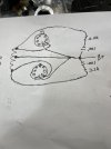
Ok am I nuts or is this wired wrong? I’ve recapped it and the b+ still drops down to about 250v from 360v very quickly. If I pull the output tubes the voltage stays. Im sorry for my terrible drawing but I’ll try to explain. The b+ goes straight to pin 4 of the outputs. Then to the output transformer center tap. Then the legs of the output transformer go to pin 3 and to this resistor /capacitor network and back to b+. Full b+going to the screen? Am I wrong? Is this not a 6l6 amp? I have 236v on pin 3 and 247v on pin 4.
 

Attachments

  • IMG_3751.jpeg
    IMG_3751.jpeg
    84.1 KB · Views: 12
  • IMG_3750.jpeg
    IMG_3750.jpeg
    185.6 KB · Views: 12
Back
Top Bottom