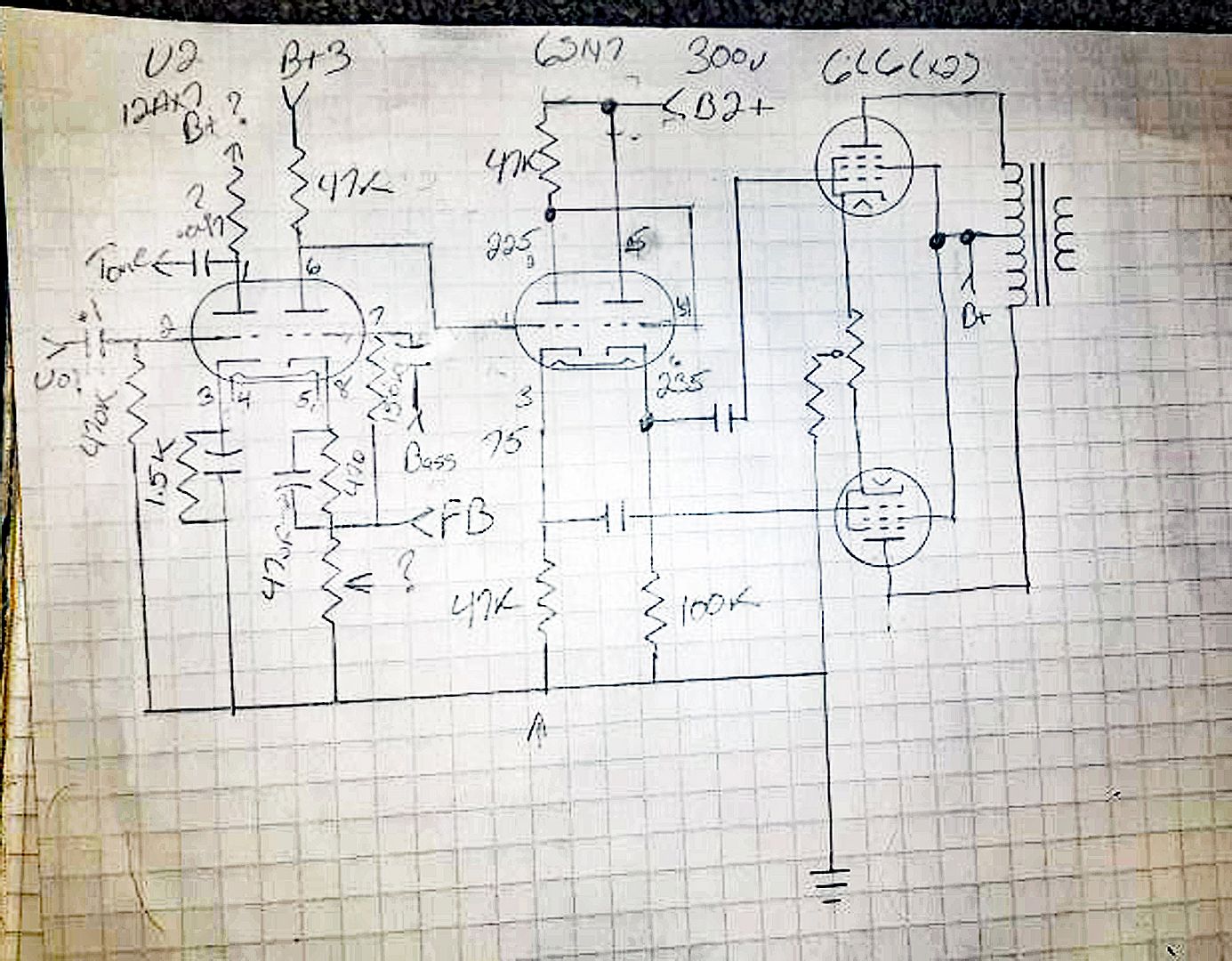
ok so I banged together a test circuit for that inverter. I made the assumption that the B+ supply is 300 volts, mostly because that seemed like a reasonable enough number.
I rigged up a 6M pot to bias the grid since I had no other way of doing it.
With the pot set so that about 1/2 the plate voltage drops from plate to cathode and 1/4 across the plate and cathode resistor I get the following voltages
1 - grid 2 -3.5 volts from grid to cathode (can't measure this directly, meter loads it down too much)
2 - plate 2 +225v
3 - cathode 2 +75v
4 - grid 1 +225v
5 - plate 1 +300v
6 - cathode 1 +235v
Its not completely unreasonable, but the current is a little on the low side for a 6sn7. The inverter side is about 1.5ma and the cathode follower side is about 2.3ma. With a 6SN7 at those voltage levels closer to 10ma would be typical.
I didn't pass any AC through it but its not going to have any gain. Actually it will have slightly less than unity gain, so for every 1v in about 0.9v will come out as measured to ground.
I didn't have one to try, but this may fare better with a 6SL7.
Still not sure what to think about the input, I'm guessing it is actually direct coupled to a 12ax7 plate since thats the only thing that really makes any ind of sense here. If the plate of the 12ax7 is about 71-72 volts, that would work fine. Thats not a lot of overhead though.