• The move to the new server is done. There are some software and database maintenance updates in process. This has us passing the hat around to help out. We appreciate any donations. Seriously, even a dollar helps. The payment page may be found here - https://www.audiokarma.org/support.html

6l6 mystery amp

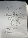
Ok, so on the 6sl7, can you gi e us voltage readings on each pin? Also if you can map out whats connected to each pin that would help.
 
Ok, so on the 6sl7, can you gi e us voltage readings on each pin? Also if you can map out whats connected to each pin that would help.
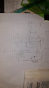
Ya I can get them tomorrow I’ll try to make a diagram. I was going to try to make a schematic but I’m really not good at it. Maybe a tube at a time it might make sense.
 
I also sent a signal to the pin 1 of the 6sn7 through a capacitor to kill the dc current and I go a sound from the speaker. Nothing from the grids of either of the 12ax7’s so I think the problem is in the 12ax7’s
 
the pin 1 wiring makes no sense. Thats the grid from triode 2, and it looks like its being fed from a resistor from B+? It also appears to be going to a grid of a 12ax7 which also makes no sense. If thats actually a tie to ground it would be logical. There would have to be a cap coming in to pin 1 from a plate or something though.

2 is a triode 2 plate, appears direct-coupled to the grid of the triode 1 which works. The 47k is a reasonable seeming plate resistor value

3 is triode 2 cathode. Resistor to ground at that value would make sense if its a split load, so would the cap. But thats not how this is being used it seems.

4 is triode 1 grid, direct coupled to triode 2 plate, kosher

5 is triode 1 plate, direct to B+ and the tie point for triode 2 plate's resistor. This is fine if triode 1 is being used as a cathode follower. Why, NFC, it makes no sense

6 is triode 1 cathode, resistor to ground for cathode follower operation. Cap apparently out to the grid.

The other two are heater and those are what they are.

I've never seen a tube rigged like this but it seems like it would function as a phase inverter other than the pin 1 stuff. The balance is probably way screwed up though, and its not going to have much gain. I have no idea why you'd wire something this way. Pin 2, the plate, will be 180 out of phase from the grid. Signal at pin 3 will be at the same phase as the signal at grid pin 1. That out of phase signal is direct coupled to the grid of the second half of the tube, and outputs from the cathode where it is the same phase as the grid so your two outputs are 180 out, but without making any sort of in-depth effort to analyze the circuit it just doesn't seem to me that it would be equal but opposite phasing. There also won't be much voltage gain with such a large cathode resistor on the first triode section.

the voltages on the 4,5,6 pins are definitely not workable though. The plate must be the highest voltage on a triode, and the grid needs to be a few volts lower than the cathode. As-shown the grid is 10 volts above the plate and almost 50 above the cathode. Thats absolutely not going to work but it will do a bang-up job of nuking a tube.

1-2-3 doesn't make sense for the same reasons.

also you have pin 2 at 210v and the other end of the wire at pin 4 at 250, so something is wrong there.
 

Attachments

  • 20240615_101934.jpg
    20240615_101934.jpg
    58 KB · Views: 5
Last edited:
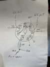
the pin 1 wiring makes no sense. Thats the grid from triode 2, and it looks like its being fed from a resistor from B+? It also appears to be going to a grid of a 12ax7 which also makes no sense.

2 is a triode 2 plate, appears direct-coupled to the grid of the triode 1 which works. The 47k is a reasonable seeming plate resistor value

3 is triode 2 cathode. Resistor to ground at that value would make sense if its a split load, so would the cap. But thats not how this is being used it seems.

4 is triode 1 grid, direct coupled to triode 2 plate, kosher

5 is triode 1 plate, direct to B+ and the tie point for triode 2 plate's resistor. This is fine if triode 1 is being used as a cathode follower. Why, NFC, it makes no sense

6 is triode 1 cathode, resistor to ground for cathode follower operation.
It's like, "Was there another tube type in this socket?"

Man! The schematic would be so nice.
 
It does pass sound through the 6sn7 but it doesn’t seemed amplifier at the speaker. I can hook the wave generator up to the speaker and it’s about the same volume. I don’t mind starting with a fresh schematic but I’d like to keep the tone controls if possible but I’m not even sure about these 12ax7’s
 
when in doubt, make your own schematic.

Or just reset to a bare chassis and build it to a known schematic.
There are plenty of nice, well-documented push-pull 6L6 amps to choose from.

It would also make it much easier for online people to follow what is happening and then give cogent advice.

Yeah! I used "cogent" in a thread! :thumbsup:
 
There are plenty of nice, well-documented push-pull 6L6 amps to choose from.

It would also make it much easier for online people to follow what is happening and then give cogent advice.

Yeah! I used "cogent" in a thread! :thumbsup:
Ya I’m sorry I can provide more info on it. As you can see I can’t draw to save my life I also don’t have too much time to work on it at the moment to get a good schematic. I think I’ll be starting over though. I’m wondering is this is actually why they sold it.
 
Ya I’m sorry I can provide more info on it. As you can see I can’t draw to save my life I also don’t have too much time to work on it at the moment to get a good schematic. I think I’ll be starting over though. I’m wondering is this is actually why they sold it.
I'd say that is a possibility, like 99%. ;)
 
I'd be willing to wager quite a lot of projects have been sold because they didn't work for whatever reason and it was beyond someone's interest or ability to figure it out. I've absolutely seen it with cars.


anyway, cheater trick for drawing schematics, they make stencils that you can use to get things reasonably neat. My drawing skills are poor too, but anyone can trace a stencil and make it not look like a complete disaster.
 
So i took a drive and was contemplating this. This is ultimately a split load inverter with a direct coupled cathode follower. I don't know whats happening at the input but if some corrections ate made ok think this should operate, maybe with some value tweaks. I need to put the boat back together now that I've had lunch but maybe I'll try to breadboard this to see what makes sense.

Its mostly that input setup that bothers me. The grid does need to be positive from ground, but less positive than the cathode. The usual method is to tap out of the cathode resistor somewhere with a high value resistor to the grid.

I don't quite understand the point of the follower honestly. I suppose its the argument about the unequal drive impedance that a split load provides but i don't know if thats a real problem or just a theoretical one. Lots of things use it with no issues
 
What I did notice is that the negative side of the preamp heater circuit was connected to ground. I assumed this was a mistake so I disconnected it. The preamp heaters are rectified to dc and in their own circuit except where the negative side went to ground. I don’t know if that means anything.
 
Back
Top Bottom