
Carbsandcaps
Super Member
Brand new I just replaced all of the electrolytics. It uses a choke then a 47uf capHow old are the main filter caps?


Brand new I just replaced all of the electrolytics. It uses a choke then a 47uf capHow old are the main filter caps?

Did you try pulling all the tubes except the 6L6GC tubes and measuring the B+?I tested the ac voltage coming out of the transformer and it doesn’t drop at all when the dc voltage drops 100 volts. Is that normal?

Yes! The choke installed right after the rectifier may drop the B+ voltage. It might be nice to know its specs.wait, its a 5U4 direct to a choke, then a cap, or is it a cap to ground, then a choke, then another cap?
Choke input supplies with very little load run much higher voltages and drag down when loaded to their design current flow, though all of your measurements that show current flow indicate its drawing stupid amounts for unclear reasons.
Yes! The choke installed right after the rectifier may drop the B+ voltage. It might be nice to know its specs.
By the way, this power supply design is called a Choke Input filter. Several online articles describe how they work and how to design one.
https://www.diyaudio.com/community/threads/using-choke-in-choke-input-power-supply.249797/
https://www.aikenamps.com/index.php/chokes-explained
If the choke is causing an excess voltage drop, you may need to redesign the power supply by using the proper choke or switching to a capacitor input filter.Ok so could the choke be wrong and causing the voltage drop through saturation? I could bypass the choke and see what happens. I’ll look for numbers on it tomorrow.
Good luck!Ok that would make sense since there’s nothing else in the circuit right now. I’ll bypass it tomorrow and see what voltages I get.


 www.vivatubes.com
Your choke might have more DC resistance than the nominal value.Ok so I bypassed the choke and the voltage shot up to 480v! I found the part number and the choke is supposed to be a 60ohm 4h choke. It measures out to 80ohms and 5.6h. I’m not sure exactly what would cause that voltage drop though.
Vintage Stancor C-1412 Filter Choke Transformer 4H 250mA 60ohm
Your source for vacuum tubes, electrical components and all things audio. Fast shipping. Satisfaction Guaranteed.

Worth a try.choke input supplies are approx 0.9x the AC voltage, cap input are approx 1.4x. Its nothing to do with DC resistance, its just how chokes work. On this one the transformer isn't high enough in voltage for a choke input supply to make any sort of sense unless its meant to run a 6v6 or other lower voltage output tube.
This isn't really a choke input type choke, its a secondary filter. There should be a cap upstream of it. For choke input on something with highly variable current demands like an amplifier you want something called a swinging choke. Thats why things are changing so much. Put the choke back in, put a cap to ground off the rectifier, it'll behave itself.
choke input supplies are approx 0.9x the AC voltage, cap input are approx 1.4x. Its nothing to do with DC resistance, its just how chokes work. On this one the transformer isn't high enough in voltage for a choke input supply to make any sort of sense unless its meant to run a 6v6 or other lower voltage output tube.
The inductance changes with current flow too, so an unloaded number isn't going to jive with the datasheet spec unless you load it with the specified current.
This isn't really a choke input type choke, its a secondary filter. There should be a cap upstream of it. For choke input on something with highly variable current demands like an amplifier you want something called a swinging choke. Thats why things are changing so much. Put the choke back in, put a cap to ground off the rectifier, it'll behave itself.
Good luck! Hope this fixes the problem.Ok cool ill try it now I was reading about chokes last night and I read something about swinging chokes but didn’t get to deep into it
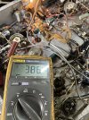
You guys are THE BEST! Voltage is almost perfect with a 47uf 500v cap at the rectifier. I’ll put the rest together, replace the rest of the caps and report back. One of these days I’ll figure this electricity thing out.
