
This is not correct.I have the pots centered. I removed the caps from pin 5 and it still has low voltage. With full b+ to the screens and lower voltage on the plates isn’t that going to make the tube flow like crazy?
Oh, to have the schematic...



This is not correct.I have the pots centered. I removed the caps from pin 5 and it still has low voltage. With full b+ to the screens and lower voltage on the plates isn’t that going to make the tube flow like crazy?

Usually, the screen voltage is part of the main power supply. One tap off the main transformer.I did find another tap out of the transformer that was taped up it’s got 360vac it shared the center tap with the other tap that’s being used. I wonder if I should use that for the screen voltage instead


its honestly not uncommon to feed the screens from the same place the transformer comes from. Maybe not ideal, but it can be done, and having the screens 5v or so higher than the plate thanks to drop within the transformer isn't unheard of. UL designs also typically have screen voltage slightly higher than plate voltage for the same reason. Triode-wired also runs screen equal to plate voltage for obvious reasons. Thats not why this is being dumb, though its possibly something that can be tweaked later and might want to be depending on what the output transformers actually are. We're just dealing with idle conditions here which is way less complex.
54v / 310R = 175 ma per pair or 87.5ma per-tube. Somehow making the resistor larger has increased the current by 50ma per pair which just isn't possible. Since the plate voltage is up it seems like the current has dropped though. Since the pot is 150 ohms, thats about 75 ohms per side at 87.5ma so there is an extra 6.5 volts across that, so basically 60 volts cathode to ground.
just plugging some numbers into a tube curve calc, assuming 360 cathode to screen and plate, and aiming for 87.5ma it should be about 25 volts from cathode to ground, and you're clearly well above that. Given 350v at the plate and an expected ~60 at the cathode, thats only 290 volts across the tube which would need even less bias voltage.
Something is wrong. I don't know whether its measurements or what but this just does not make sense.
Can you confirm the grids are at zero volts and that its not oscillating? Maybe yank whatever tube is immediately upstream of all this, or unhook the coupling caps from the upstream stage to make sure we're not chasing the wrong problem here.
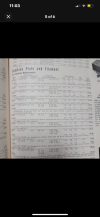
I'm not following you. Could you enlarge that page and highlight the transformer you are talking about?The coupling caps are all out, there’s .1vdc on the grids. Is it possible that this is a 6v6 amp and not a 6l6? Here’s the specs on the power transformer. It’s rated at 250ma. It’s the r-35bc View attachment 3224288
I'm sorry, but I'm still not following you. A 250mA PT would work in a 6L6GC push-pull pair amp --- IF there weren't too many other sub-circuits in the unit drawing current.

I'm sorry, but I'm still not following you. A 250mA PT would work in a 6L6GC push-pull pair amp --- IF there weren't too many other sub-circuits in the unit drawing current.
But this doesn't address your voltage reading issues. (I don't think).
I have nothing on the output transformers. They look like a multi impedance design. I can’t tell which wire is which and some of them are tied together but I thought that dc couldn’t be affected by a transformer. They’re all tied to this organ style speaker plugI'm unsure if it matters with your amp, but do you have a proper resistor or speaker load on the output transformer?
No dim bulb. Straight to the wall.is this running through a dim bulb tester by any chance?
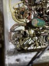
I think that you should put a load onto the secondary. Either a dummy load (resistor) or speakers.I have nothing on the output transformers. They look like a multi impedance design. I can’t tell which wire is which and some of them are tied together but I thought that dc couldn’t be affected by a transformer. They’re all tied to this organ style speaker plug View attachment 3224469
