• The move to the new server is done. There are some software and database maintenance updates in process. This has us passing the hat around to help out. We appreciate any donations. Seriously, even a dollar helps. The payment page may be found here - https://www.audiokarma.org/support.html

6l6 mystery amp

That's not a swinging choke, so it really shouldn't be a choke-input supply. However, if that's a 5U4 rectifier, 47uF might be a bit high. 10-20uF would be easier on the rectifier. It wouldn't be a bad idea to stack two 47uF/350VDC caps in series, with 150K/2W across each cap to balance the voltage across them. That will give you c. 23uF and plenty of headroom for any turn-on surge.
I used a 47uf only because it was the only 500v rated cap I had. I can replace it with a 22uf but they’re rated at 450 and this thing spikes at 500v on start up.
 
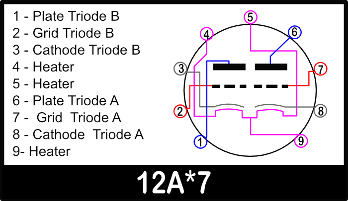
Ok my voltages are all good and I’ve got it all recapped. Now I have no sound. I’ve been looking at the pinouts at the 12ax7’s and I noticed on the 12ax7 right before the 6sn7 has a capacitor coming off pin 7 and going to pin 9. This uses 12v to pin 4 and 5 so pin 9 is technically not used but it’s still between the heaters. I don’t understand what the circuit is here. The feedback circuit goes to pin 9 as well. Could this not be a 12ax7 setup?
 
Ok my voltages are all good and I’ve got it all recapped. Now I have no sound. I’ve been looking at the pinouts at the 12ax7’s and I noticed on the 12ax7 right before the 6sn7 has a capacitor coming off pin 7 and going to pin 9. This uses 12v to pin 4 and 5 so pin 9 is technically not used but it’s still between the heaters. I don’t understand what the circuit is here. The feedback circuit goes to pin 9 as well. Could this not be a 12ax7 setup?
The 12AX7 does use pin 9 as part of the heater connection. Your amp has a 6.3VAC heater line, correct? The 6.3VAC line is wired so that the two triode heaters are in parallel, yielding 12.6VAC.

Pins 4 and 5 are one connection to the 6.3VAC line. Pin 9 is the other.

12ax7%20pin%20out%20configuration%20ecc83.jpg
 
It uses a 12vac tap then goes through a selenium rectifier to pins 4 and 5 so pin 9 is not used as the heater connection. However there is a capacitor connected from pin 9 to pin 7 from the feedback circuit. IMG_3779.jpeg
 
I used a 47uf only because it was the only 500v rated cap I had. I can replace it with a 22uf but they’re rated at 450 and this thing spikes at 500v on start up.

Sure that makes sense. In the long run I think a lower value and higher voltage tolerance might keep the 5U4 happier. Even a 10uF film cap would probably be fine.
 
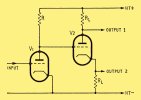
I’m really starting to regret buying this amp! The 6sn7’s feed the 6l6 grids from their cathodes. That’s pins 3 and 6. The grid of the 6sn7 comes directly from the plate of the 12ax7 before it with no capacitor so the 6sn7 grid has 200v on it. Does any of this make sense or should I start rewiring it? IMG_3782.jpeg
 
so before we get to that point, what sort of voltage do you have across the cathode resistor in the output stage, and what value is that resistor?


if the output stage is in cutoff or saturation it won't pass signal no matter whats going on with the tubes upstream of it.
 
so before we get to that point, what sort of voltage do you have across the cathode resistor in the output stage, and what value is that resistor?


if the output stage is in cutoff or saturation it won't pass signal no matter whats going on with the tubes upstream of it.
I’ve got 17v going across the cathode resistors I put the original 100ohm back in. I know it’s too much and one of the tubes is starting to red plate. If I send a signal straight to the output tubes it comes out of the speakers but low volumes. One channel is putting out 160v ac at full signal input using a signal generator.
 
I’ve got 17v going across the cathode resistors I put the original 100ohm back in. I know it’s too much and one of the tubes is starting to red plate. If I send a signal straight to the output tubes it comes out of the speakers but low volumes. One channel is putting out 160v ac at full signal input using a signal generator.
160 VAC on the speaker terminal connections?
 
Ok scratch that. I don’t know where it was reading 160vac from but I’ll let you know if it comes back. Right now it’s under 1v on the speaker terminals
 
I can’t get a signal though anywhere else. The 6sn7 has voltage on every terminal and will blow my signal generator (don’t ask how I know that!) nothing comes through when I put a signal to the 12ax7 grids. I’ve got 230vdc on the cathodes of the 6sn7’s
 
I can’t get a signal though anywhere else. The 6sn7 has voltage on every terminal and will blow my signal generator (don’t ask how I know that!) nothing comes through when I put a signal to the 12ax7 grids. I’ve got 230vdc on the cathodes of the 6sn7’s
Okay. Maybe it is best to go back to the beginning. Did this unit ever work at one time? If so, what modifications do you know of? What were the symptoms before you started measuring voltages?

You cannot communicate with this ex-RCA engineer or anyone who may know him to learn more about the amp and maybe get that precious schematic. :idea:
 
Supposedly it “passed a signal”. I bought it from someone who got it from the “rca engineer”. I’ve asked the seller some questions but he knows little about it. He said his tech brought it up to low voltage on a variac and that’s when it passed a signal whatever that means. Basically I think im on my own here (with your guys help of course).
 
If I had to guess, this was someone’s project for trying different things. It has capacitors from 3 different eras, and an oddball circuit. Seems like he was messing with it when he had time. It had no tubes in it when the person I got it from got it. So they guessed at the tube compliments.
 
Supposedly it “passed a signal”. I bought it from someone who got it from the “rca engineer”. I’ve asked the seller some questions but he knows little about it. He said his tech brought it up to low voltage on a variac and that’s when it passed a signal whatever that means. Basically I think im on my own here (with your guys help of course).
"Passed signal" could mean he put voltage on the input and got voltage on the output --- whether the voltage is proper or not --- who knows. :idea:
 
If I had to guess, this was someone’s project for trying different things. It has capacitors from 3 different eras, and an oddball circuit. Seems like he was messing with it when he had time. It had no tubes in it when the person I got it from got it. So they guessed at the tube compliments.
It would be best if you had the correct schematic.

The guy you got it from may have tried to get it running (with an audio output) and failed. He could make more money if the darn thing worked as it was designed.
 
It would be best if you had the correct schematic.

The guy you got it from may have tried to get it running (with an audio output) and failed. He could make more money if the darn thing worked as it was designed.

I agree with a diagram it would probably be up and running by now. As much as I would love to see it work as designed I’m also tempted to rewire it to a more conventional circuit design.

I’m very skeptical that it ever worked with the power supply not even putting out the correct voltage to begin with.
 
It might be best to look for another project. One with the documentation and history, which makes things much less frustrating.
 
Back
Top Bottom