• The move to the new server is done. There are some software and database maintenance updates in process. This has us passing the hat around to help out. We appreciate any donations. Seriously, even a dollar helps. The payment page may be found here - https://www.audiokarma.org/support.html

A tale of two Fishies - X-101-C integrated amp restorations

Dave and I had a conversation and I've asked him to expose my errors rather than politely passing over them.
I probably made a couple of dumb mistakes while redoing some resistors. :yes:

Don't even try to tell me you've never made mistakes under the chassis. :grumpy:
 
Last edited:
Really good troubleshooting Dave. These threads are always educational for me.

Don't even try to tell me you've never made mistakes under the chassis. :grumpy:

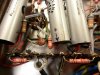
Don, I have this pic of a blown cap that I wired backwards to remind me of the many mistakes I've made under and above the chassis.

attachment.php
 
Performance Issues Resolved

All of the original performance issues noted in the ratrig have now been resolved. As Don mention, we had a conversation in which he asked me to post all of my findings, not only for the learning possibilities they present, but also for the overall teachable moment the process provides as well. Here then are the areas I addressed to return the unit to its stock performance capabilities, in the general order in which they were addressed:

1. The 12AX7 phono preamp tubes and 5751 line/tone amp tubes were swapped to place the original specified tubes in the line/tone amp positions. This was done in an effort to address the significant sensitivity issues noted during initial testing. While the swap helped the sensitivity somewhat, it was still nowhere near specification.

2. Initial testing also showed a rising power output characteristic in the right channel only. Since it occurred at a thermal rate of climb, effort was then focused on the line/tone amp tube for that channel, where the TungSol 12AX7 was found to be very bad. It has been replaced with a temporary good replacement, which completely resolved the rising power output issue.

3. Initial testing also showed a variance in power output between the channels, which lead to testing of the 7591s. Of the four originally intended for installation, one was found to be quite weak, and of the two sent along as spares, one was bad. The four remaining four good tubes were then matched and reinstalled as decently matched pairs. This effort then produced nearly equal power output capabilities in both channels. However, it was also noted that the left channel developed a parasitic oscillation when both channels were driven. It was noted for later service efforts.

4. The Phase Inverter adjustments were then made, but it was noted that one control required rotation to one extreme to produce the lowest THD reading. It also let out quite a SNAP/POP when I did that. While no harm was done, it was also noted for later service.

5. An examination was then made underneath, where it was first determined that the AC heater circuit was still referenced directly to an output tube cathode, rather than the new cathode buss created when individual cathode sampling resistors were installed. While this generally doesn't cause any problems, it is still a discrepancy from ideal (relating to noise), and so was corrected.

6. Also noted was the manner in which the Screen Stability Resistors were installed. Rather than having each resistor power a screen terminal from a new buss, the resistors were installed daisy chain fashion, so that the first tube saw 100 ohms, the second 200 ohms, and so on through to the last tube. Correcting this installation then allowed both channels to produce identical maximum power output levels, and caused the Phase Inverter adjustments to be nearly centered now for optimum performance.

7. Further investigation showed that the resistors making up the NFB networks were reversed in each channel. This was causing not only the parasitic oscillation noted in the left channel, but the extreme loss of sensitivity since this reversal caused the NFB level to increase by a factor of about 5. Correcting this then returned normal sensitivity levels, and eliminated all traces of the oscillations noted earlier.

8. The last items noted were a cathode resistor in the line/tone stage of the left channel that was marked as one value, measured another, but in either case, was wrong. This was corrected to the proper value. Also noted was a B+ dropping resistor that was increased in an effort to achieve the operating voltages noted on the schematic.

This is really a practice that should be avoided. All of the small signal stages in all classic designs are cathode biased, which makes them largely insensitive to operating voltages with respect to gain produced. If operating voltages are of concern, then the best approach is to adjust the voltage to the entire unit -- not try to individually adjust each B+ distribution point. It is of limited value in the overall scheme of adapting a unit to today's higher line voltages, and in many instances, can actually hurt performance. The adjusted resistance was changed back to the original value.

Finally, the cantankerous phase inverter control was removed, disassembled, cleaned, reinstalled, and adjusted, with no further incident.

These efforts then allowed the unit to perform as originally designed. There are (obviously) some remaining modifications installed in the unit. But these are not such as to detract from stock measured performance. In total then, they include:

1. Installation of output tube cathode sensing resistors.

2. Installation of screen stability resistors.

3. The phase inverter coupling caps have been doubled in size, while the output tube grid return resistors have been reduced to 220k (from 330K).

4. The line stage coupling caps to the tone stacks has been doubled.

5. Phono preamp modifications have also been installed, which have not been measured or evaluated at this point.

In all then, this is a perfect example of how including measured performance with sonic evaluations can result in achieving the best overall performance from a given unit. Measurements and specifications do matter, as we don't always hear deteriorations in performance until it often achieves excessive levels. Don used this unit for close field low level listening use, so the defects were likely unnoticed -- but they were there none the less, and detracted significantly from the unit's original capability. Don has stated he wants to up his game in the performance measurement side of this hobby, so all of the preceding is offered as help in that vein.

For the moment then, listening tests will now be conducted on the repaired unit, while thought is given to best ways to proceed from here for improved performance, and interface into today's audio world. That project will be documented in a new thread devoted to that effort.

Pics include:

1. The heater connection error, and the daisy chained style Screen Stability Resistor installation can be seen in this before shot of the left channel output tubes.

2. The heater connection has been corrected, while the Screen Stability Resistors have been relocated on the tube sockets, using pin #1 as a buss terminal at each socket.

3. The original feedback network wiring, where close inspection will show that the 1000 ohm feedback resistor, and 220 ohm feedback load resistor have been inverted in each channel.

4. The feedback wiring has all been corrected in this shot, as has the resistor noted in the final pic. Individual channel power output with all the corrections in place is now 28.89 watts per channel in both channels, while 1 kHz distortion -- even with only 1/5th the feedback in place -- remains relatively the same at .75% average per channel at the onset of clipping. This is a perfect example of the fact that just like seasoning, some feedback is great, but too much spoils the pot. In this case, the instability issues caused by the excessive feedback canceled out any extra distortion reduction benefit it was providing. Clean power with both channels driven remains a rather timid 14 watts RMS, while distortion is over 1.5% in each.

5. What's up with this guy? Indications are that it's an 8.2K resistor, it measures 1.2K, and is supposed to be 1.5K. It can be seen as corrected at the very right in pic #4.

So, that's about that. Time for listening tests, and pondering. Output stage testing is complete now, with no doubt that its performance can be improved significantly, but that will be addressed in the new thread.

Dave

 

Attachments

  • Repaired X-101C 001.jpg
    Repaired X-101C 001.jpg
    98.2 KB · Views: 91
  • Repaired X-101C 002.jpg
    Repaired X-101C 002.jpg
    98.3 KB · Views: 80
  • Repaired X-101C 004.jpg
    Repaired X-101C 004.jpg
    79.7 KB · Views: 85
  • Repaired X-101C 005.jpg
    Repaired X-101C 005.jpg
    104.4 KB · Views: 85
  • Repaired X-101C 003.jpg
    Repaired X-101C 003.jpg
    85.3 KB · Views: 84
Last edited:
The link to Dave's separate thread on improving the X-101-C we are discussing is here: http://www.audiokarma.org/forums/showthread.php?t=582379


The Fisher X-101-C that Dave Gillespie updated has returned.
I've spent today listening to my Kymers X-101-C. I will continue listening to that for part of tomorrow and then put the ratrig back in and document what's the same and what's different.
 
Last edited:
Glad it arrived safely! If only for my own information, does the Kymers designation identify who you got this other X-101C from? who worked on it? or who currently owns it? And what condition is it in? bone stock? refurbished? modified?

I'm not trying to pepper you with questions, nor am I concerned about any comparison. In fact, I welcome the most detailed comparison you can make. I'm just wondering what the status is of the unit you're comparing it to, and what the designation means.

Dave
 
The Kymers X-101-C is, in fact, named for the person I got it from.

I did a power supply update, updated the coupling caps, did the phono mod, no feedback changes, no screen stability resistors, and did not replace all resistors from the volpot to the output.

It was the first one of these I updated, when I was less adventurous. I did pull the power transformer and soak it in shellac to take care of a buzz though.
All tubes are in outstanding shape . . . four very strong Westinghouse 7591s.
In some ways, it's more stock than the Ratrig was, and I'm sure it will show similar response characteristics. But I've got an April 30th work deadline that's got me working all the time right now, including this weekend.

This will be fun . . . when I get to it on the evaluation level. I pretty much know what to expect of the ratrig on the sonic level, having heard the updates to the X-1000.

Linking this thread back to Dave Gillespie's thread about what he did to this particular ratrig.
http://www.audiokarma.org/forums/showthread.php?t=582379
 
Last edited:
Great read!
I've been using a x 101-D for a while, bone stock other than power supply filter caps, but this got me worked up, and last week I replaced a lot of caps in the signal, pretty much all other than the .02 (I think they say "aerofoil") gold foil ones. After a few days, it started sounding really great!!
One question, has anyone tried to upgrade those multi disc caps in then tone section? You would have to sort of build the whole network, but it might be worth it. Or bypass the tone all together, but I find it nice to have.
 
Bryce -- if you want to know how to properly bypass the tone controls by converting the Hi Filter switch into a Tone Control Enable (or Bypass) switch, watch for the schematic of the modifications I did to Don's X-101C in the thread "Improving the Fisher X-101C". It is being drawn up into the original schematic by a fellow AKer to make for an easy understanding for those interested in doing the modifications.

Good luck with your amp!

Dave
 
Bryce -- if you want to know how to properly bypass the tone controls by converting the Hi Filter switch into a Tone Control Enable (or Bypass) switch, watch for the schematic of the modifications I did to Don's X-101C in the thread "Improving the Fisher X-101C". It is being drawn up into the original schematic by a fellow AKer to make for an easy understanding for those interested in doing the modifications.

Good luck with your amp!

Dave

Will check it out! Maybe a full bypass would be the move
 
Did the full bypass, pretty cool to have it on the hi filter switch! But,,, I think I like it with the tone switch in. I've been always running it with the loudness switch on, with that off and the tone section bypassed, it sounds pretty good, but with tone in, it sounds way too much midrange, ad the loudness and the lows and way top fills in. Maybe it's my speakers, klipschorns, they can be a little unruly sometimes, or the room.
New coupling caps, K40s in the phono and M150, silver mica's are sounding great!!
 
Interesting -- I've found that with the tone controls bypassed, it brings in the lowest octave with much more authority on material that has that information available. How did you bypass the controls?

Dave
 
My observation about the loudness control is that it bring in upper bass. With the tone controls set to flat and the loudness off, a bit of that mid-bass bump is still evident. With the tone controls out, the bottom is there, but it is much more dependent on the material being played.
So, I have the tone controls completely bypassed because I prefer it that way.
 
I just split a line off after the .02 cap, right before it's sent to the REV output rca in the back, so it's still went to the tone section, but also to that high filter switch. Then the .047, after the make up for the tone section, is sent the the other side of the switch, the switch then feeds into the main volume. So one way you have bypass, and the other, you have stock.

@audiodon, mine has very little bass with the loudness off, it's very drastic, maybe there is some weird about mine
 
Bryce -- that approach certainly does bypass the tone control section. Although I'm wondering -- how even does the volume remain between the two switch settings?

One other thing to consider with this approach, is that the absolute polarity of the signal changes as you change from normal to bypass. Sometimes that can't be helped, while other times, it can be dealt with. Just be aware that in your unit now, since the original design changed polarity from the selectable inputs to the speaker outputs with the tone controls in the circuit, the way you have elected to bypass the tone controls, with them removed from the signal path, the unit then does not change phase overall.

Thanks for sharing the details of your work, and good luck with it!

Dave
 
Bryce -- that approach certainly does bypass the tone control section. Although I'm wondering -- how even does the volume remain between the two switch settings?

One other thing to consider with this approach, is that the absolute polarity of the signal changes as you change from normal to bypass. Sometimes that can't be helped, while other times, it can be dealt with. Just be aware that in your unit now, since the original design changed polarity from the selectable inputs to the speaker outputs with the tone controls in the circuit, the way you have elected to bypass the tone controls, with them removed from the signal path, the unit then does not change phase overall.

Thanks for sharing the details of your work, and good luck with it!

Dave

Aaaahh, I didn't think about that.. I guess with getting rid of that make up gain stage I've changed polarity. The volume doesn't change too much, just a little drop with the tone out. It sounds really good with it out, more even and natural really, I just like them in, seems to add a little more excitement.

The switch allows the volume pot, the one side that's not ground, to either get feed from the .047 cap (stock, after the gain stage and tone), or the .02 cap form the gain stage before tone section and reverb in/out
 
Bryce -- Anytime you have a switching event cause a notable change in gain with otherwise similar sound quality between the settings, the natural human reaction is favor the setting with higher gain -- if only because it makes the volume control action (and therefore the unit overall) feel more responsive. That is the reason that such switching events should seek to minimize as much apparent gain change as possible between the settings.

As for your concern for the LF response of the unit, if you left the built in LF filter in the circuit, then bypassing the tone controls will not produce the improvement that could otherwise be had on LF material, due to the fact that this filter is placed before the tone controls in the circuit.

Also, you might go back and target the sections of this thread regarding HF response through the various inputs, as it is very obvious from initial testing that this unit was NOT designed to have the line and tone amplifier stages each operate flat with respect to frequency response. Rather, the line stage response compensates for the response losses in the tone amp stage, in an effort to present an overall flat response to the power amp section when the tone controls are centered.

This approach can work well enough as long as both stages are always working together in the circuit. Without compensating for this design approach however, simply bypassing the tone controls AND tone amp stage as you have will produce an amplifier with a rising HF response from the line amp section, rather than an overall flat response that a tone control bypass modification is trying to achieve. This too then would add to an already soft LF response impression.

None of this is intended as any criticism towards your efforts, but the exercise does show precisely why simple modifications to bypass the tone controls, without taking into account how their circuits contribute to the larger overall response picture, can produce mixed results in the end. Such modifications really require a complete examination of the circuit driving, and receiving their output to produce the desired outcome.

In this case, once the limitations of the low and high filter circuits are removed, the response of the line and tone amplifier stages are both equalized for flat response, and the in/out switching is made to occur with minimal change in effective gain levels (and without a change in signal polarity if possible), then the tone controls can truly be seen for the audible impact they produce. My experience was that they notably limited the LF information on material that contained significant energy at that end of the audio spectrum.

As a final thought, realize too that the loudness circuit (when on) only attenuates certain frequencies, giving the impression that other frequencies are boosted -- when in fact, those frequencies are simply no longer being attenuated. The distinction is an important one: It is hard to emphasize what is not there in the first place, as the loudness function happens after all of the line and tone stage circuits in the design. This is why the loudness function primarily emphasizes mid bass frequencies, which can then lead to a bass boom, rather than a natural extension of bass frequencies.

On the other hand, since the effort with Don's amplifier included flattening the response of all stages in the amplifier, when the tone controls are removed from the signal path in that scenario, the full frequency spectrum is then equally amplified, and a complete sonic picture is presented. With that result, the loudness function was only found to be of benefit at the very lowest listening levels.

Now that Don has had the amplifier for a while, he may (or may not) have more to add regarding this topic. However, I believe like him, I found the tone control defeat setting of the modified unit to be very balanced across the audio spectrum, producing a very full and detailed presentation (no response holes), that was quite satisfying sonically.

Dave
 
Bryce -- Anytime you have a switching event cause a notable change in gain with otherwise similar sound quality between the settings, the natural human reaction is favor the setting with higher gain -- if only because it makes the volume control action (and therefore the unit overall) feel more responsive. That is the reason that such switching events should seek to minimize as much apparent gain change as possible between the settings.

As for your concern for the LF response of the unit, if you left the built in LF filter in the circuit, then bypassing the tone controls will not produce the improvement that could otherwise be had on LF material, due to the fact that this filter is placed before the tone controls in the circuit.

Also, you might go back and target the sections of this thread regarding HF response through the various inputs, as it is very obvious from initial testing that this unit was NOT designed to have the line and tone amplifier stages each operate flat with respect to frequency response. Rather, the line stage response compensates for the response losses in the tone amp stage, in an effort to present an overall flat response to the power amp section when the tone controls are centered.

This approach can work well enough as long as both stages are always working together in the circuit. Without compensating for this design approach however, simply bypassing the tone controls AND tone amp stage as you have will produce an amplifier with a rising HF response from the line amp section, rather than an overall flat response that a tone control bypass modification is trying to achieve. This too then would add to an already soft LF response impression.

None of this is intended as any criticism towards your efforts, but the exercise does show precisely why simple modifications to bypass the tone controls, without taking into account how their circuits contribute to the larger overall response picture, can produce mixed results in the end. Such modifications really require a complete examination of the circuit driving, and receiving their output to produce the desired outcome.

In this case, once the limitations of the low and high filter circuits are removed, the response of the line and tone amplifier stages are both equalized for flat response, and the in/out switching is made to occur with minimal change in effective gain levels (and without a change in signal polarity if possible), then the tone controls can truly be seen for the audible impact they produce. My experience was that they notably limited the LF information on material that contained significant energy at that end of the audio spectrum.

As a final thought, realize too that the loudness circuit (when on) only attenuates certain frequencies, giving the impression that other frequencies are boosted -- when in fact, those frequencies are simply no longer being attenuated. The distinction is an important one: It is hard to emphasize what is not there in the first place, as the loudness function happens after all of the line and tone stage circuits in the design. This is why the loudness function primarily emphasizes mid bass frequencies, which can then lead to a bass boom, rather than a natural extension of bass frequencies.

On the other hand, since the effort with Don's amplifier included flattening the response of all stages in the amplifier, when the tone controls are removed from the signal path in that scenario, the full frequency spectrum is then equally amplified, and a complete sonic picture is presented. With that result, the loudness function was only found to be of benefit at the very lowest listening levels.

Now that Don has had the amplifier for a while, he may (or may not) have more to add regarding this topic. However, I believe like him, I found the tone control defeat setting of the modified unit to be very balanced across the audio spectrum, producing a very full and detailed presentation (no response holes), that was quite satisfying sonically.

Dave

Hmmm, ok, but the amp seems much flatter with the controls out, and looks that way one the scoop as well. It's a little cleaner sounding too, I just like the way it sounds with it in, might be my speakers or room, I've never heard the amp with anything else. The LF filter is a little different in this amp also, seems it was changed at one point, but it sounds really good with all the controls out, but, maybe I should put them in if it's not supposed to run like that. It has low end with all the stuff out, really flat all the way down, but at low volumes I do like the loudness in, even if it's a bump not at the very bottom. I don't listen to it very loud.
About the volume change, that doesn't bother me, I'm a recording engineer and everything you change seems to make a volume change. When someone wants to change something, you can always turn the speakers up a few clicks and ask, is that better? The answer is always yes, so I'm used to trying to take the change of volume out of the decision, it would be very hard to work otherwise.
I'm really liking the amp as it sits now, better than my Scott 299c and eico HF81 on the same speakers and room, and I really loved those amps. So I might not change it for a while, even if it might be wrong, it just sounds really good.
 
No problem. I just wanted you to be aware of my findings versus what your efforts are working to produce. Understanding that then, if it is working well for you in your environment, then that is what really matters.

Good luck with it!

Dave
 
I'll try and get more into it running with out controls, but I do really like it the way it is. might take me a while to take it apart and modify it some more, but hope I don't make it a boring sounding amp.
 
Back
Top Bottom