• The move to the new server is done. There are some software and database maintenance updates in process. This has us passing the hat around to help out. We appreciate any donations. Seriously, even a dollar helps. The payment page may be found here - https://www.audiokarma.org/support.html

A tale of two Fishies - X-101-C integrated amp restorations

That's it a Digital multimeter like the radio shack one I have, and you do all this unplugged wow!

Tube
 
Last edited:
Where have all the Fishies gone . . .
long time passing
where have all the Fishies gone
long time ago
where have all the Fishers gone
Gone to Dave's house,
every one
When will we ever learn?
When will we ev ... er learn?
:beatnik:
 
Yeah, I know. It's been a while. But the Bogen project is on the run now, so the 101C is coming up to bat very soon. It's a project I'm really looking forward to -- much less involved than that taken on with the X-1000 and Bogen projects. Stay tuned.....

Dave
 
I'm going to see if I can get Eduarsan to document Dave's updates for the cathode bias to fixed bias with EFB conversion on a schematic.

Dave will get to this after he uses the sun to melt what we usually remove with a snowblower.
 
The Ratrig -- First Impressions

So after much time and ado, I finally unboxed the ratrig yesterday for the first time, and got it on the bench to see just what I was getting into. The love and attention required to bring this unit to the condition it is currently in is nothing short of monumental. What an amazing story it's had to date!

Between last night and this morning, I've completely reread this thread to get some history, and studied Don's folder of information to get a handle on the design of the X-101C.

Conceptually, it is the audio section of (likely) a late model 400 receiver (measurement of the OPT will tell that tale), but with push-button input selection, cathode bias, and a powered center channel output. Otherwise, with the exception of small details, the topology is identical with one exception. In this model, Fisher chose to hang the Hi Filter network on the first line stage, meaning that the recording output signal will be affected by the setting of this switch. Normally, Fisher applies the Low Filter network on that stage, which too, can then affect the recording output signal. Ideally however, these are playback controls, and should not affect the signal to be recorded at all. The power supply is classic SS Fisher.

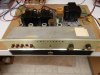
Since this unit has had a thorough going over and recapping, I thought I'd just throw the tubes in and turn this sucker on. The small signal tubes were marked as to location, so they were carefully installed accordingly. The output tubes were not so marked, so they were just installed randomly. Proper loads were connected, and 117 vac power was applied.

After letting the unit warm up for about 10 minutes, some very basic initial tests were run. The left channel by itself produced 22.6 watts RMS at 1 kHz, with .40% THD -- not too bad, but required a whopping line level signal of 1.45 vac to achieve it. Hummmmm.

The right channel was an eager beaver, achieving 25.0 watts by itself at 1 kHz, but produced .80% THD in the process. It too required a very high input signal to achieve this power output level. And there was something else strange about this channel, too. When a preset full power signal is applied instantly, the power output is initially much lower, with power rising over time. HMMMMMMM. Swapping the output tubes between the channels did not swap this problem, so it is something unique to that channel. The left channel did not display this problem.

I also noted that Don specified 5751 tubes in the Line/Tone stage position, which have a lower amplification factor than 12AX7 tubes do. Therefore, I swapped these tubes into the phono position, leaving the hi level signal chain using real 12AX7s as originally specified. The sensitivity improved somewhat, but not to anything near the original 300 mv specification for line level inputs.

Actually, using just one pair of 5751 tubes in either the Line/Tone or Phono stages in this unit makes it somewhat harder on 12AX7 tubes installed in the alternate position. That's because the heaters in 5751 tubes pull 17% more current than those of 12AX7s. With the heaters of these four positions connected in series then, the 5751s get robbed of heater voltage, while the 12AX7s get more. If four 5751 tubes are used, then output stage current is increased accordingly beyond the intended value at the specified 40 volt setting. No measurements have been made yet, but the issue is there none the less.

When both channels are driven simultaneously, power drops to 15 watts RMS per channel at 1 kHz, while distortion in both channels doubles, placing it close to 1 % in the left channel, and over 1.5% in the right. Both Phase Inverter adjustments were found to be set very close to optimum.

So, there's some funny stuff going on that will need to be shaken down first. This unit has the feature where the Common terminal of the output connections is NOT grounded, which makes for major headaches in testing such a unit, since the common grounds of dual channel scopes, or through green wire ground power cords of test equipment can act to short the two channels out and/or together, making testing a real nightmare. So, I want to first make sure there are no issues there causing the poor input sensitivity noted. Once that is all resolved however, the main focus of this project will then be to look at applying EFB to the power output stage to see what benefits it could bring -- plus, see what other trouble I could get into along the way. Initial indications are, it could be a lot (on both counts)!

With spring time approaching, work needs will cause this project to move with a consistent, but somewhat reduced pace. In the background will be the finish-up work on the Bogen thread going on as well. In any event, this is a project I've looked forward to, so it should be a fun ride for sure.

Stay tuned!

Dave

 

Attachments

  • Initial Ratrig Testing 001.jpg
    Initial Ratrig Testing 001.jpg
    74.6 KB · Views: 71
This is just the kind of analysis I am looking for.

Putting my student hat back on. There's always more to know and I'm out to learn!
 
Last edited:
The first mystery is solved: That of the rising power output in the right (B) channel when a preset full power signal is applied.

Remember that the phono preamp 12AX7s had been changed into the Line/Tone Amp positions, with the 5751s originally there going into the phono preamp section (all retaining channel identity) to maintain the heater string integrity, but allow all 12AX7s to occupy the small signal tube path from the line level inputs as originally designed, for input sensitivity tests. I mention this just so Don knows which tubes I am referring to here: They are the Tung Sol 12AX7s.

The rising power output symptom was only present in the Rt channel, and completely absent in the left. Swapping the output tubes did not swap the symptom -- which seemed to happen at a thermal rate of change, so a quick check of the Line/Tone Amp 12AX7s was in order -- testing both for good measure. Testing the tube at V4 (channel A) indicated it was near perfect, with a Gm of 1575 in section #1, and 1620 in section #2. I test this tube under conditions published in the RCA tube manual, where in a Gm of 1600 is specified for the published conditions used, so you can see how good this tube is. But I wasn't prepared for the results from the tube installed at V2 for the right (B) channel.

This tube produced a Gm of just 425 in section #1, and a real go-getter Gm achievement of 645 in section #2! I have NEVER seen a 12AX7 test so low -- in one section, let alone both!!

This tube has Gm indications of 1350 and 1340 (I think for the second figure) written on it, but of course I have no idea what tester this came from, or when. Assuming these two Tung Sol tubes were installed at the same time, then damage from excessive heater dissipation as discussed earlier can generally be ruled out, since its mate tests so well.

In any event, swapping these two tubes then in fact swapped the rising power output problem to the left channel, so at least that issue is resolved.

The integrity of the test equipment ground connections in light of the floating output Common connections has been verified, so the input sensitivity issue remains. I'll start chasing that one down next.

Dave
 
I've found a few weak Tung Sols recently also.
Those are probably my markings. If you keep that tube but mark it bad, I'd like to retest it. Perhaps it suffered some sort of failure - or my tester didn't and should.

I'll send some 12AX7s along to replace the 5751s and that pair of 12AX7s. They'll all be NOS Sylvanias, which is what Fisher was putting in stock as late in the game as that Fisher was produced.
Don
 
The phase inverter and power tubes have all been tested now.

The left channel phase inverter tube was solidly GOOD, with a Gm of 1525 in the weakest section, which is 95.3% of nominal (1600). The right channel phase inverter tube had both sections come in on the high end of WEAK (87.5%), with both sections measuring 1400 micromhos. This tube is still capable of performing its required function in the X-101C. For Gm, the English scale of my tester is GOOD = 90% or greater, WEAK = 80% or greater, but < 90%, while BAD = < 80%.

Of the six output tubes sent, four were GOOD, with the weakest of these producing 88.16% of Average New Power Output (ANPO). One tube was WEAK (68.79%), and one was BAD (62.20%). For power output, the English scale of my tester is GOOD = 81% or stronger, WEAK = 64% or greater, but < 81%, while BAD = < 64%.

Within the four power tubes meant for installation, three were good, while one was weak, and of the two spares sent, one was virtually new, while one was bad. By moving the tubes around appropriately, I now have four good tubes, with two reasonably matched pairs (within 10% each pair for quiescent and dynamic balance), and the two pairs matched within 5% of each other.

So now, with all tubes capable of performing their jobs from the line level inputs to the push-pull outputs, I can now get a good handle on what the original design is capable of performance wise.

Dave
 
More Testing

From the previous tube tests, I have temporarily substituted a good 12AX7 in for the defective one, and arranged the four chosen output tubes for best match up now. As a result, the original problem of rising power output in the right channel over time (which made for a moving target in pinpointing performance levels), is completely gone. With this work complete, I could now get an accurate idea of what the original performance capability of this unit really is.

With the new tube assignments in place, both channels now produce a healthy 27.56 watts RMS at 1 kHz at the onset of clipping, with .68% (L) and .65% (R) THD, when individually driven.

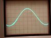
However, even worse than with the original design of the Dynaco SCA/ST-35 units, when both channels are driven, power drops to effectively 14 watts RMS per channel, which is a serious decline in performance, with distortion rising to about 1.5% in both channels. Also, in this scenario, the left channel showed an annoying parasitic oscillation under high power conditions as well. It was noted however that the AC heater system was still tied to the actual cathode terminal of one output tube in this channel (rather than the new buss point for the 10 ohm resistors), which could be the feedback path to produce this concern.

As for the operating conditions with the new tubes in place, it was noted that:

1. When operating from a 122 vac line, the use of dual CL-80 inrush limiters provided 118 vac to the primary winding of the power transformer, which is quite appropriate for the unit, with this size limiter not producing any performance limitations of the unit under maximum power conditions in both channels.

2. The main B+ produced was 456 vdc.

3. The quiescent voltage at the cathode buss was 45.6 vdc -- BUT ROSE TO 65 VDC UNDER FULL POWER CONDITIONS WITH BOTH CHANNELS DRIVEN! With the effective grid bias voltage also rising in relative lockstep to the buss voltage then, this is a major reason for the deterioration in performance when both channels are operating.

4. While each pair of output tubes created came in close enough with a quiescent match within 2 ma between the tubes in each channel (worst case), the pairs themselves showed just over a 4 ma match, with one pair averaging 37.5 ma current draw, and the other averaging just over 42 ma. At this point, the bias control has not been altered from the position it was received at.

The pic provided shows the parasitic oscillation developed in the left channel when both channels are driven.

So, a few more issues to chase down (low sensitivity and the left channel oscillation), and more tests are required on output stage operation, but clearly, there is significantly more performance that can be extracted from the X-101C.

Dave
 

Attachments

  • Left Channel Parasitic Oscillation 001.jpg
    Left Channel Parasitic Oscillation 001.jpg
    44.5 KB · Views: 39
So, there's a miswire on one output tube; Huh!

On this type of unit, my main concern, dating back to the Kymers 101-C, is how they run out of steam too early. Dave corroborates that power loss and distortion rise and will probably find a good way to counterbalance it.

What's the possibility that the rise in bias voltage from the cathodes could have shortened the life of that Tung Sol 12AX7?
 
Last edited:
Back
Top Bottom