wolfy
New Member
Hello everyone!
I would like to restore my dad’s 1979 Accuphase P260. The amplifier has had a rather hard life. As of today, it is not fully functional.
The amplifier’s history:
Now that I am a little older, my dad gave the amplifier to me; he knows how much I like it.
What I’ve done so far:
That said, I don’t know where to start with this repair . . .
I never worked on any amplifiers before and have a very basic knowledge of how they work. I am also not too good at reading schematics, especially the more complicated ones. But I am willing to learn, fully repair and restore this amplifier myself.
The first thing I want to do is get the amplifier working properly.
After that, I’d like to:

Throughout the process, I will be taking pictures and perhaps even recording videos for you.
To anyone that read this and / or is willing to help in any way, thank you!
Pictures: https://imgur.com/a/9MiOiH9
Schematic: https://www.dropbox.com/s/2oq0k6q1hi16tz9/hfe_accuphase_p-260_schematic.pdf?dl=0
I would like to restore my dad’s 1979 Accuphase P260. The amplifier has had a rather hard life. As of today, it is not fully functional.
The amplifier’s history:
- It was bought in the 80’s as fully functional.
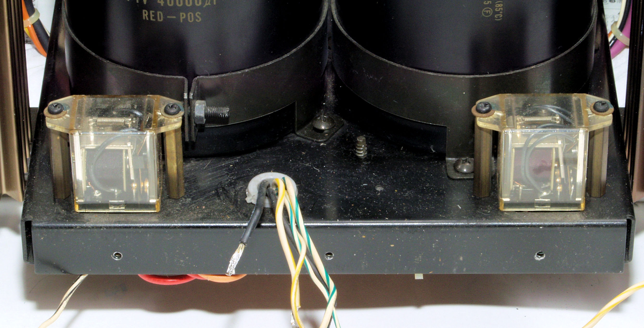
- In the 90s, the amplifier got water damaged; it was repaired: the two big (40 000uF) filter capacitors were replaced with 8x 10 000uF capacitors. The relay on the right was also replaced.
- In the 2000s, the amp was lent to my dad’s brother, who broke it by attempting to clean it.
- The amplifier was attempted to be repaired by many “technicians” who worsened the condition. It was said to be irreparable, because there was no schematic available at the time. My dad then gave up on the amplifier and put it aside.
- Few years ago, the schematic of the P260 appeared on the hifiengine.com. I managed to convince my dad to get the the amplifier fixed.
- We handed the amplifier over to a technician who replaced all the electrolytic capacitors with YAGEO capacitors; The filter caps were also replaced with Nippon Chemi-Con 2x 47 000uF 80v. VR1, VR2, VR3 trim pots were replaced on both channels.
- After the amplifier was “repaired”, it seemed to be working fine! BUT, after few undefined minutes/hours, the sound out of the left channel came out very VERY distorted and soon after the circuit protection shut of the amplifier.
- The technicians thought the output transistors were the cause, so all were replaced with SEMELAB: BUZ900 & BUZ905.
- The issue remained, the sound out of the left channel was still coming out very distorted after a certain time and the circuit protection kicked in.
- The amplifier was once again returned as irreparable.
- Then, it was then given to a family friend who found out that the LEDs on the left channel caused the amplifier disfunction. After replacing the LEDs (D3 & D4) on the left channel only, the amplifier was finally repaired and worked well for couple of years.
- Few days ago, the Accuphase P260 had developed a problem. The sound out of the right channel comes out distorted (reminds of a dying tweeter), but the circuit protection doesn’t kick in. The left channel works fine.
Now that I am a little older, my dad gave the amplifier to me; he knows how much I like it.
What I’ve done so far:
- Check the DC offset on both channels.
- The DC offset on the right channel is very unstable: when the amplifier is first turned on the offset is ~40mV. However, as the amplifier gets warmer, the offset starts dropping, after few minutes it settles at around ~30mV. After letting the amp idle for few hours, the offset drops ~10mV below 0.
- The DC offset on the left channel seems to be okay-ish I think. It fluctuates between 5mV and -5mV, but mostly it is around 1.5mV. I would like to fix that too. Chase it closer to 0mV and keep the fluctuations at a minimum. But for now, the right channel is a priority.
- The DC offset was tested with the amp in the normal mode, but similar behavior happens in the CLASS-A operation.
That said, I don’t know where to start with this repair . . .
I never worked on any amplifiers before and have a very basic knowledge of how they work. I am also not too good at reading schematics, especially the more complicated ones. But I am willing to learn, fully repair and restore this amplifier myself.
The first thing I want to do is get the amplifier working properly.
After that, I’d like to:
- Put the original Hitachi 2SK134 & 2SJ49 output transistors back in, as they are probably working just fine!
- Replace all the YAGEO electolytics with audio grade capacitors,
- Replace the relays,
- Wash it clean,
- And perhaps have the enclosure repainted / polished.
Throughout the process, I will be taking pictures and perhaps even recording videos for you.
To anyone that read this and / or is willing to help in any way, thank you!
Pictures: https://imgur.com/a/9MiOiH9
Schematic: https://www.dropbox.com/s/2oq0k6q1hi16tz9/hfe_accuphase_p-260_schematic.pdf?dl=0
Last edited: