• The move to the new server is done. There are some software and database maintenance updates in process. This has us passing the hat around to help out. We appreciate any donations. Seriously, even a dollar helps. The payment page may be found here - https://www.audiokarma.org/support.html

Accuphase P-260 repair & restoration (help)

Thank you. I will have my friend from the UK order these for me, since I am from Bosnia & Herzegovina (Sarajevo) and the shipping costs $120 to here.
For now, I will replace the D3, D4 and see how it goes.

If it's not a big hassle, could you explain what the trim pots (VR1, VR2, VR3) on the L & R channels do?
I would also like to learn how to know how to adjust the dc offset and the bias.
 
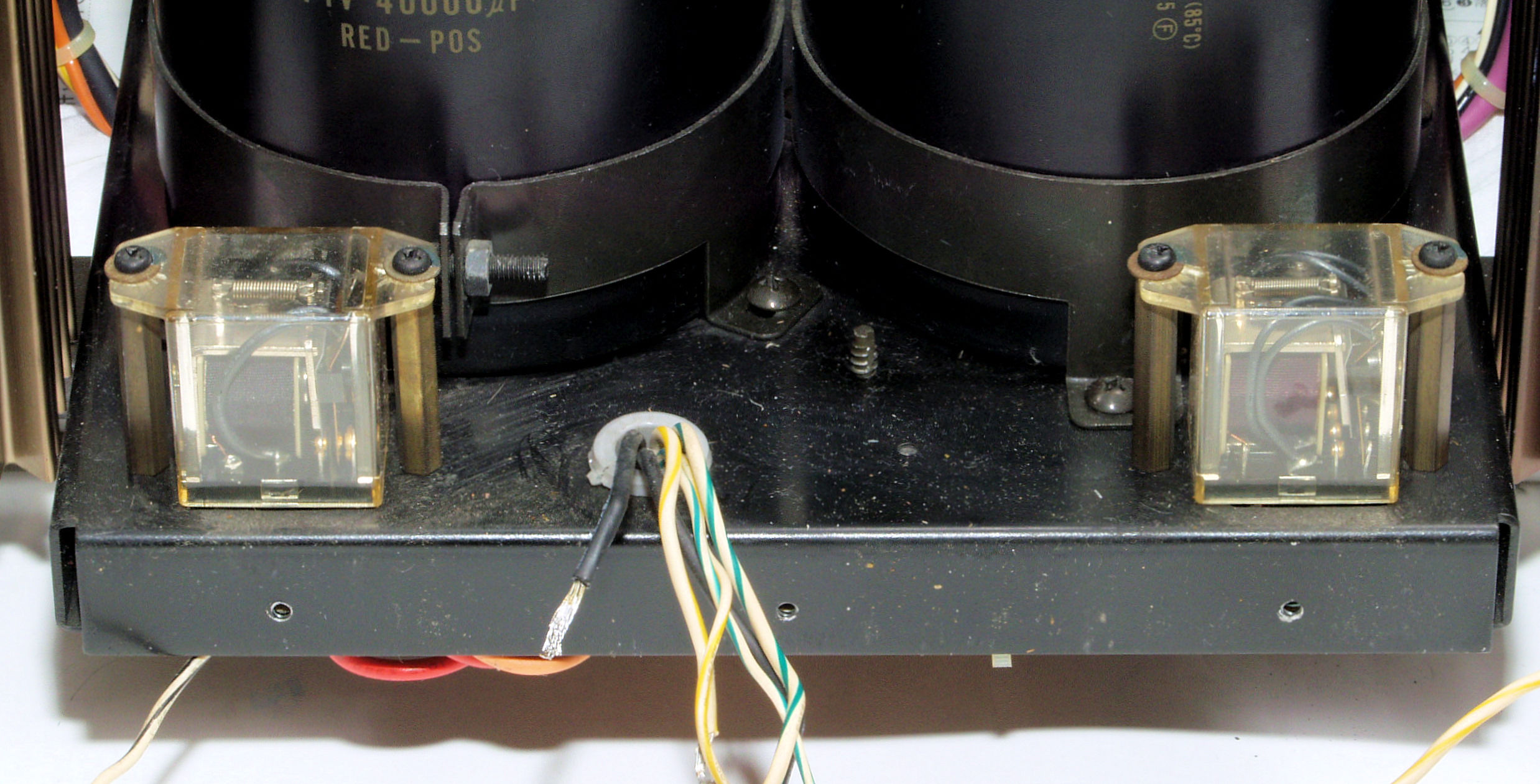
This is the original relay that is installed in the amplifier right now. So relays like these can also mount the chassis too:
Lr0Fait.jpg


Do you think that both relays like these are available somewhere in the EU? Like Mouser?
 
Last edited:
This is the original relay that is installed in the amplifier right now. So relays like these can also mount the chassis too:
Do you think that both relays like these are available somewhere in the EU? Like Mouser?
These may work but.....There is always a but ! You will need to shuck the plastic covers and reuse the old plastic cover.Don't break it.Or use the stand offs and mount the other way.
https://www.digikey.com/product-detail/en/omron-automation-and-safety/MY4F-DC24/Z10477-ND/1814314
 
I managed to do some work on the amplifier today after uni.

I replaced the LEDs today with super bright LEDs I had in stock AND I also repaired few cold solder joints.
The results are amazing. The DC offset on the right channel is "normal" compared to what it used to be.

When I first took the right channel apart, I witnessed some true horrors:
I instantly noticed the 4 cold solder joints:
dQLzv56.jpg


Then, at this place, one of the technicians damaged the board while soldering.
I don't know if you can see it, but the lower left solder pad is lifted up a little:
uM1r5D3.png


Finally, I replaced the old LED's with new ones:
Y5yAYjo.jpg


Then, I partially assembled the amplifier and tested it.
After I let the amplifier warm up, I tested the DC offset:
Right channel:
EfbU5Y5.jpg


Left channel:
qaxPWFI.jpg


I also measured the temperature of both channels. What's weird is that the right channel's temp is lower for about ~10C.
Right channel:
0hrS0ON.jpg

Left channel:
3SOwSKV.jpg


- - - - -

I gave the amplifier a quick listen (neighbors :boring:), and the amplifier seems to be working fine. The sound is no longer distorted. I'll give it a proper listen tomorrow.
HOWEVER, I am still not happy with the results. The DC offset on both channels still fluctuates, from about 8mV to -8mV.
Would you say this is normal and as good as it can get?
What can I try to do have minimize the dc offset fluctuations and chase it closer to 0mV?
And why is the right channel colder than the left ? Could it be the difference in the LEDs?

Also, I'd like to thank you all again for helping me through this repair / restoration!
Any further advice is welcome. :D
 
Last edited:
I also measured the temperature of both channels. What's weird is that the right channel's temp is lower for about ~10C.
Check your idle current/bias/quiescent current..For both channels and adjust accordingly.
 
Without a value, you would have to use a signal generator and oscilloscope. Adjustments are done through vr2 and vr3 one for class A one for Ab.

I would go through those solder joints with a fine-tooth comb, take the old solder off with good quality desolder wik clean the solder pad with isopropyl alcohol and a q-tip also clean the legs of the unsoldered components with q-tip and the alcohol also if needed a sharp scalpel, antistatic precautions need to be taken here. Then use a good solder station and some (again) good quality 60/40 solder to solder back on.
 
Last edited:
Without a value, you would have to use a signal generator and oscilloscope. Adjustments are done through vr2 and vr3 one for class A one for Ab.
Thank you very much!

I have a question, should the bias be adjusted with the amp idle?
If adjusting bias is done through VR2 & VR3, I am guessing the VR1 is for the DC offset adjustment?

I would go through those solder joints with a fine-tooth comb, take the old solder off with good quality desolder wik clean the solder pad with isopropyl alcohol and a q-tip also clean the legs of the unsoldered components with q-tip and the alcohol also if needed a sharp scalpel, antistatic precautions need to be taken here. Then use a good solder station and some (again) good quality 60/40 solder to solder back on.
I am going to buy a desoldering gun. I found it REALLY hard to get the old 40 year old solder out of the solder pads I fixed. The old solder was stone hard and the little pump would barely move it . . . :dunno:

I am going to carefully clean each pad and component legs, like you advised, once I get them desoldered.

I have thought about replacing the 5% carbon resistors. I heard they "age"; that their value increases over time. So with a hope of making the amplifier more stable, I thought about changing all 1/4w resistors with 1% metal film resistors, specifically Vishay Dale RN60, is that too crazy?

I've also thought about the electrolytic caps I want to replace:
For power supply: Nichicon PW or HE
For the L&R channels: Elna Silmic II

Would you say that is a good choice?

P.S. Past few days I've been listening to the Accuphase a lot, it works good, but I am positive it can do much much better! :biggrin:
 
Get everything working as it should be first then change components, however no problem planning ahead,

Nichicon PW or HE or combination of both are fine choices for the PSU, for the amp cards people like the Nichicon FG range or Elna RFS (Silmic II) me I'd use the Nichicon PW or Panasonic FC range for a couple of reasons, class A mode means higher temperature the FG and Silmic's are 85oc rated caps the PW and FC are 105oc rated caps and the signal doesn't go through an electrolytic capacitor as far as I can see, so no need for 'special caps' as it were.

Resistors I would just leave alone unless any have been replaced badly before.

Unless your going to spend many hundreds on a desoldering tool, use this brand of desoldering wik width between 1.5-2mm https://uk.farnell.com/chemtronics/80-2-10/desoldering-braid-1-5mm-3-0m/dp/860736 do not use a hand desoldering pump you could pull the pads off the board
 
Get everything working as it should be first then change components, however no problem planning ahead,

Nichicon PW or HE or combination of both are fine choices for the PSU, for the amp cards people like the Nichicon FG range or Elna RFS (Silmic II) me I'd use the Nichicon PW or Panasonic FC range for a couple of reasons, class A mode means higher temperature the FG and Silmic's are 85oc rated caps the PW and FC are 105oc rated caps and the signal doesn't go through an electrolytic capacitor as far as I can see, so no need for 'special caps' as it were.
I am still little confused about the bias adjustment, should it be done with the amplifier in idle? And is the DC offset adjusted with VR1?

I saw that no electrolytic caps were in the signal path, but I thought that they would still matter somehow. The amplifier in class A does get very got, up to 70°C, I'll go with the PW or HE for the L&R channels too.

Resistors I would just leave alone unless any have been replaced badly before.
I have noticed that one resistor was replaced with 2 resistors in series by one of the previous technicians. I don't know why.

Unless your going to spend many hundreds on a desoldering tool, use this brand of desoldering wik width between 1.5-2mm https://uk.farnell.com/chemtronics/80-2-10/desoldering-braid-1-5mm-3-0m/dp/860736 do not use a hand desoldering pump you could pull the pads off the board
I found 2 affordable desoldering guns:
One is from Duratool: station + gun:
https://cpc.farnell.com/duratool/d00672/desoldering-station-uk-eu-plug/dp/SD01384?st=ZD-915

And one from eBay which has good reviews:
https://www.ebay.com/itm/S-993A-220...248438?hash=item4d7af35236:g:r78AAOSw2QZdHHio

Do you think either of them would do the job?
 
Last edited:
I'm curious too as I just got hold of an old Accuphase P-260 recently. It's a very nice build piece of equipment.

I think the DC offset of 8mV is negligible, it's just 8 microwatts of power at an 8 ohm speaker. As long as it's slow changing (temperature) and not noise I wouldn't be concerned really.

My P-280 unfortunately has one dead channel and sadly the PCB is damaged by some very hot components :(. It seems the problem has occurred in the first / second stage of the end-amp. A quick measurement indicates the big MOSFETs still seem okay.

I will replace the burnt resistors, most caps and the transistors which have suffered from the high current and the components which suffered from the heat.

Will post updates! :beerchug:
WhatsApp Image 2023-02-12 at 14.30.58.jpeg WhatsApp Image 2023-02-12 at 16.24.14.jpeg
 
Back
Top Bottom