• The move to the new server is done. There are some software and database maintenance updates in process. This has us passing the hat around to help out. We appreciate any donations. Seriously, even a dollar helps. The payment page may be found here - https://www.audiokarma.org/support.html

across the bench: an electronic menagerie of diagnostic oddities plus photos and design analysis

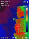
citation 16 thermals, lower bias setting (not 60c nuke spec in manual).

hk cit 16 - 34.jpeg
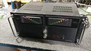
view of face plate and both amp boards, front to back.

hk cit 16 - 35.jpeg
even with the lower bias setting the mains txf per channel heat up as if they are under-sized.

hk cit 16 - 36.jpeg
temps between channels seem to be even, not many hot spots on the amp boards.

will bump up the final bias setting to a slightly higher temp and evaluate idle wattage from there.
 
citation 16 just about done, pair of carbon comp need to go on one of the amp boards and then final tuning before dynamic output testing and placing the amp on the outbox shelf.

hk cit 16 - 37.jpg
reflowed all the solder joints on each display board and changed out the flickering/unstable power indicator lamps with LEDs.
 
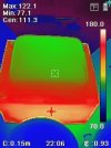
thermals after exercising the citation 16.

hk cit 16 - 38.jpeg
all of the 3.9k resistor match now, 5w upgrade. bias still set low, sinks comfortably cool before adjusting prior to exercise.

hk cit 16 - 39.jpeg
chassis hasnt heat soaked yet after running 4r load and pulling 215w peak from the mains with a few bass heavy tracks.

hk cit 16 - 40.jpeg
overall heat generation is manageable although dc bias is of some concern possibly highlighting more components that need updating that the "kit" completely ignored.

hk cit 16 - 41.jpeg
txf's get noticeably hot and that heat radiates to the new power caps which had a surface temp of 100f at this point (txf side). a thin wall of heat shielding between the two would cost almost nothing (dollar store solution) and improve power cap lifespan noticeably.
 
yet another cj pv5 discovery and design alteration/upgrade.

cj pv5 - 27.jpg
the mje 340 that gets mount to the oddball looking heat sink has some surface area deficiencies.

cj pv5 - 28.jpg
moderate amount of space for an alternative heat sink to be mounted. q1 hasnt been updated with a ztx component yet (200c rated), still the mps transistor in this photo (left side of red 3w resistor).

cj pv5 - 29.jpg
the replacement sink is probably oversized by a little too much but it dropped the operating temp by 50f, instead of cooking at 200f constantly. improved surface contact vs the original plus using proper mica isolation and mx-2 thermal grease.
 
final thermals of the pv5 utilizing the oversized heat sink upgrade.

cj pv5 - 30.jpeg
the 820k 3w (x2) parallel resistor mod, 129f vs 170f with the first replacement since the original carbon comp took a flight 52 meg ohms from home.

cj pv5 - 31.jpeg
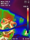
attempting to get a measurement on the new mje 340. its hottest spot being 146f seems better than the 200f with the original heat sink. with the top removed from the chassis this is obviously best temperature scenario since the system can breath at its convective maximum. soon as the pot belly stove lid goes on things will cook.

increased air space throughout the updated circuit board should help with air flow just about everywhere. changing the relay to low heat solid state device might be a future modz option plus relocating most of the power supply to its own outboard chassis (like the recent cary preamp) will help as well. again, a better designed cover like audio research would help immensely but only if the stock pv5 design errors are addressed first.

and thats the end of this modz project, someone is going to have a lot of sonic fun with this system, far beyond the 100-500 hour thermal failure estimate of the original design. only time will tell for certain.

 
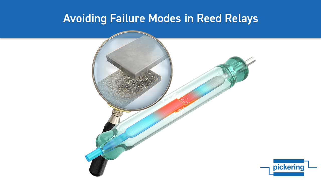
researching reed relays and why they should be avoided for audio gear. seems like there are a few models that use a problematic reed relay.


a quick look at 12ax7 biasing curves, not for any particular reason.

 
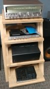
the stack of mac stuff has changed a little bit but it was a slow summer.

zshow - 01.jpg
just some eye candy filler until the next batch of audion photos are ready.

zshow - 02.jpg
sansui g-9000, threshold fet nine, adcom gfa-555 and mcintosh 752 (should have taken its cage off).

zshow - 03.jpg
a better shot of the mac amp.
 
on a side note, the importance of changing out film safety caps (rifa in the video) when using aged bench electronics.

youtube.com/watch?v=GDTuHDsHHFA
*hp 4195a network/spectrum analyzer example.


differences between x and y class film safety caps.
Timely post there^^^. A friend recently gave me a Tektronix 2215 oscilloscope that had been stored in his garage for some number of years. About ten minutes after powering it up, a RIFA cap on the current limit board gave up the ghost with a pop and an awful smell.

Storage of the scope in a non climate controlled garage surely encouraged the drama as these caps in particular don't do well with moisture. RIFA caps are still being made and from what I've gathered, the newer ones are fine to use as replacements. If nothing else, I guess the newer ones aren't 30 years old!

From what I've read, RIFAs should be at or near the top of your "replace on site" capacitor list, especially if the unit has been hibernating for a number of years.
 
top of your "replace on site" capacitor list, especially if the unit has been hibernating for a number of years.
standard procedure for all things electrolytic oddly enough, even after 3-5 years which is far worse than any film. when in doubt change it out, seems applicable as well.

it feels odd to think of a digital storage scope as being vintage, that aint right. feels so unnatural but then again saying that my birthday was last century... we are not going to go there, things get weird quickly.


it was interesting to do a deeper dive into film cap failure modes, helps with future r&d and audio gear modz.
 
Not surprised, just doesn't look like nearly enough area to dissipate the heat 200+200 watts can produce.
 
thermal management nightmare.
an all too common "feature" with audio gear regardless of design age/era. an epoch of thermionic self destruction might be another way of viewing things.

the cube would make for an interesting GaN amp or latest igbt generation (mad scientist edition) test bed/chassis to take things up to or beyond 1kw 8r mono ability. but... some of my "pure digital" brain storming designs will most likely live on a scrap piece of paper for decades to come.

hmm, 1kw output into open baffle speaker design rated for 105db efficiency. should be enough kick for those pesky quiet passage classical tracks or pipe organ (theater organ) dynamics. lets see what math says about theoretical db output, 3db per doubling of wattage so 2/4/8/16/32/64/128/256/512/1024 will be 10 steps times 3db each or 30db of potential on top of the speaker efficiency. although minus 2db per meter away from the source (3m = -6db) even though something resembling a line array might have lower db losses per meter.

*not the same as a tiny open baffle experiment, useful info though.
 
full rated power bench testing
gotta love life experience as it helps to shape future purchases.

doesn't look like nearly enough area to dissipate the heat
this is a moment of engineering common sense. now if only the consumer product engineer would have had the same moment.

carver's designs might have been for duty cycle of load vs heat generation but massive amounts of heat will be created even if the drum beat lasts for half a second, several times per minute and several minutes per track. time to put the kettle on, should have boiling water half way through the next track unless its mickey hart (planet drum).


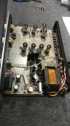
some audion sterling class-a tube amp updates.

audion - 13.jpg
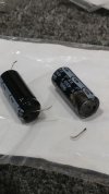
another electrolytic in bad condition, looks like it was leaking for a while. the lead fell out when desoldering, not sure it was still connected prior to extraction.

audion - 14.jpg
the process of relocating some resistors to a different location. large white blobs are the new 47k 2w resistors (now 7w). also the green goblin on the right side is a 4.7k 5w to replace the resistor that shed its skin as shown in an earlier post.

audion - 15.jpg
new power caps that are not samwha. 100r power resistors bumped up to 10w vs 7w original (not much of an improvement). new resistors not sitting on the pcb, air gap helps.

need to photo document all component values since zero schematic in existence. tried to contact the company directly about a month ago, nothing but silence. flying blind on this one, not all traces connected by traces. some require a neighboring component lead to complete the circuit bridge, careful when desoldering and forgetting.
 
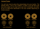
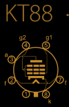
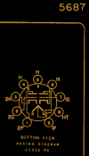
audion manual calls for the following bottles: kt90/kt88, 6922, 5687 (mk1 version)

Screenshot 2024-10-03 at 02-53-00 sterling mk2 manual.doc - sterling__mk2_english.pdf.png

will be installing kt88 for outputs since there are a few floating around the tech bench. if the initial testing is favorable i.e. a non-chernobyl event horizon, then a pair of matched kt90 may be acquired. this amp should complement the experimental open baffle speakers shown a few pages ago. might use a tube based mac amp for the 2x2 15 inch drivers to complete the bi-amp ensemble.


 
revisiting tube amp design components, output txf and the importance of impedance matching.

Screenshot 2024-10-03 at 10-14-28 Output Transformers - The Heart of a Tube Amp.png

Screenshot 2024-10-03 at 10-23-51 Biasing a Tube Amplifier Amplified Parts.png


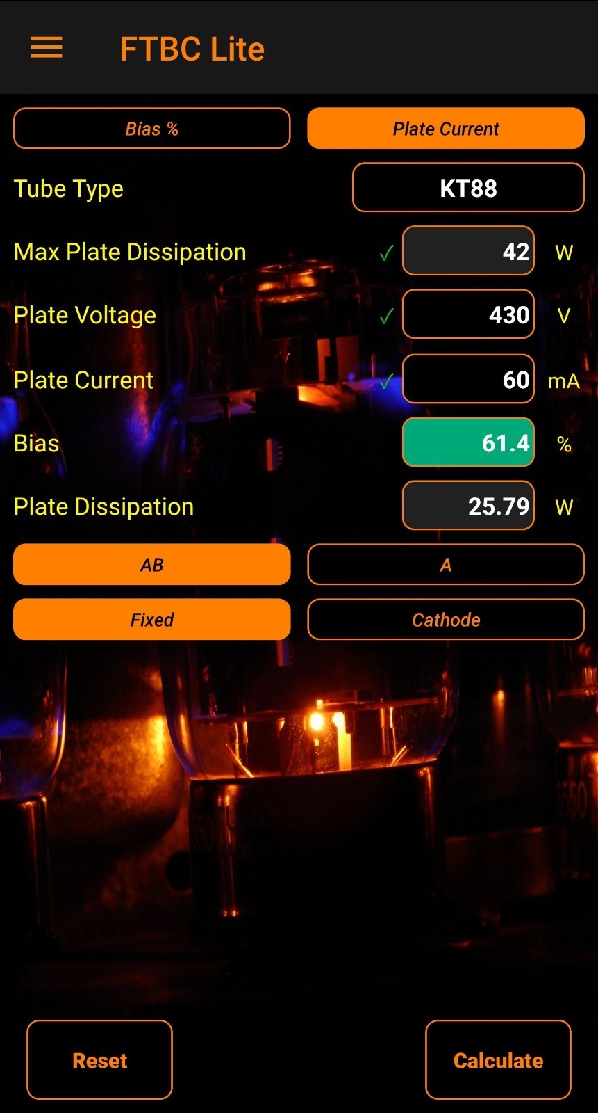
since the audion mentions class-a operation chances are the output tube bias is going to be a little bit unhealthy, and no pots to adjust (fixed bias). time to do some resistor hunting and bias calculations.
 
Back
Top Bottom