• The move to the new server is done. There are some software and database maintenance updates in process. This has us passing the hat around to help out. We appreciate any donations. Seriously, even a dollar helps. The payment page may be found here - https://www.audiokarma.org/support.html

across the bench: an electronic menagerie of diagnostic oddities plus photos and design analysis

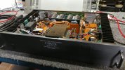
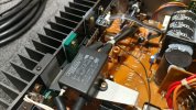
inside the m-1.0t amp.

carv c1_m1 - 07.jpg
chassis might be small but there is a healthy amount of wattage contained within.

carv c1_m1 - 08.jpg
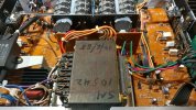
december of 88 marked on the txf. also some nelion update boards.

 
a few more photos of the carver m-1.0t amp.

carv c1_m1 - 10.jpg
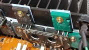
the heat sink seems a bit undersized for so many outputs in close proximity but that does not appear to be a problem for bob's amp design. mk2 series upgrade board as well.

carv c1_m1 - 11.jpg
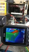
2x4 spacer between amp and preamp to help show thermals, left channel.

carv c1_m1 - 12.jpg
right channel, both temps taken after exercising both pairs of bench speakers in parallel (at high volume).

carv c1_m1 - 13.jpg
tdk noise filter for mains, nice part number for future reference and projects.

overall a dynamic duo of audio gear with a decent noise floor (silent) and lots of wattage ready for action. should be a fun combination when paired with the large polk sda srs in the demo chamber.

 
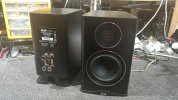
testing some elac bookshelf speakers.

elac carina - 1.jpg
elac carina bs243.4

Screenshot 2024-09-09 at 11-55-52 Carina Bookshelf BS2434 Best Audiophile Speakers.png

the speakers have a surprisingly good bass response for such a small driver. it also helps to use an amp with sufficient power reserves and ability, mcintosh ma7900 in the demo chamber seems to do ok.


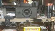
adjusting the bench speakers.

jbl bench - 1.jpg
instead of under the bench now they will be on the shelf, shoulder height.

jbl bench - 2.jpg
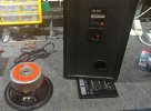
these were jbl800 but the original woofers had zero foam surround remaining so some salvage drivers were utilized.

jbl bench - 3.jpg
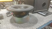
8 inch subs (x2) from a monitor audio powered sub that had a major design flaw plus the plate amp expired in a predictable fashion, as they (most brands) usually do.
 
the initial problem was stated as sound cutting out.

cj pv5 - 04.jpg
this system uses an output relay, good place to inspect.

cj pv5 - 05.jpg
this electrolytic does not look healthy, seems to have wet the bed and now there is a puddle of corrosion.

cj pv5 - 06.jpg
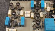
overall this tube preamp appears to have low hours on it since the board hasnt started to discolor like a previous pv5.
 
some pv5 bottles and part numbers.

cj pv5 - 07.jpg
tung-sol 12ax7 for the phono front end.


cj pv5 - 08.jpg
some tung-sol 5751 for line stage.


cj pv5 - 09.jpg
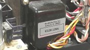
mains txf with part number c126-128a for future reference.


*wow, i see more than a few issues with this project. probably best that i remain quiet about it.

*comment #1 has some info.

 
measuring some caps on the pv5.

cj pv5 - 12.jpg
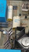
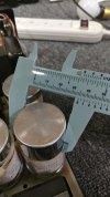
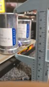
the usual important data when shopping for replacements, 60-90uf 500v

cj pv5 - 13.jpg
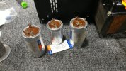
rather large physically not to mention desoldering will be a challenge without damaging/lifting any traces.

cj pv5 - 16.jpg
the corroded relay circuit cap and its LCR status, not good. looks like a root cause to me.
 
original caps removed without issue or pcb damage.

cj pv5 - 17.jpg
the four tab cathode connections can makes things difficult, good thing this is not a double sided board.

cj pv5 - 15.jpg
belly pan could use some cleaning. the new 500v caps are sitting on the left side of the photo/bench.

cj pv5 - 14.jpg
bottom of the board fairly clean and showing low hours of use i.e. no burned pcb areas yet.

in terms of a longevity mod an interesting thought would be to relocate the txf and do a detachable umbilical from main chassis to a outboard power supply box, like the cary SLP-98 posted a few pages ago. either source a larger va txf or do a high efficiency smps which would open up much need air space in the tube heated main chamber.
 
finishing up the pv5 repairs.

cj pv5 - 10.jpg
watching the bottle temps.

cj pv5 - 11.jpg
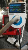
mains idle wattage although not at exactly 120v. dim bulb disconnected.

cj pv5 - 18.jpg
much more space with the new power caps installed. the 1.2k resistor near them hits around 260f during normal operation.

anti-riaa board on the left side for testing the phono section, signal passes through all 8 tubes. sounds slightly better vs the line stage input, lots of gain either way.
 
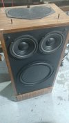
pair of older polk speakers with the time alignment feature.

polk 12b - 1.jpg
polk rta 12b speakers with one driver held in place by 1 of its 4 screws, to indicate which driver needs repair. also the tweeter removed from its perch.


polk 12b - 2.jpg
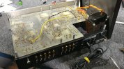
installed some dayton drivers to test cabinet for bass response, woofers almost fit (4r+4r wired in series, no rta connection).

polk 12b - 3.jpg
cabinets have seen better days and so have the speakers, chunk missing from surround on the right driver. other cabinet in 1st picture a driver has detached voice coil from spider illness.

polk 12b - 4.jpg
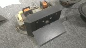
the tweeter assembly is easy to remove, thumb friendly hardware.

polk 12b - 5.jpg
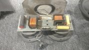
crossover has more than a little going on.

polk 12b - 6.jpg
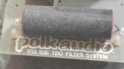
the only place i could find a model model designation, nothing on the cabs just left and right designations.


pair of older polk speakers with the time alignment feature.

View attachment 3297376
polk rta 12b speakers with one driver held in place by 1 of its 4 screws, to indicate which driver needs repair. also the tweeter removed from its perch.


View attachment 3297387
installed some dayton drivers to test cabinet for bass response, woofers almost fit (4r+4r wired in series, no rta connection).

View attachment 3297388
cabinets have seen better days and so have the speakers, chunk missing from surround on the right driver. other cabinet in 1st picture a driver has detached voice coil from spider illness.

View attachment 3297389
the tweeter assembly is easy to remove, thumb friendly hardware.

View attachment 3297390
crossover has more than a little going on.

View attachment 3297391
the only place i could find a model model designation, nothing on the cabs just left and right designations.


And that crossover mounted fuse looks a bit too hardy (too high of amperage rating) like it had been haphazardly replaced sometime back in its abusive user history for a speaker of that size !
I didn`t look at the speakers specifications, just didn`t look right, like it might be a "~ 10 amp" 32 v from the picture !
 
And that crossover mounted fuse looks a bit too hardy (too high of amperage rating)
that is a good point, the fuse element seems oversized to protect a tweeter (normally low wattage consumption) or even the time aligned woofer in the cabinet (single wire direct feed).

if the previous owner(s) were blowing fuses on a regular basis it is possible something larger was installed which has a rather predictable outcome. like duct taping a 20a breaker since it keeps kicking, what could possibly go wrong (hello house fire).
 
looks like i will be examining the fuse in the not so distant future.


*brochure info

*note to self: rta = real time array not real time alignment...
 
that is a good point, the fuse element seems oversized to protect a tweeter (normally low wattage consumption) or even the time aligned woofer in the cabinet (single wire direct feed).

if the previous owner(s) were blowing fuses on a regular basis it is possible something larger was installed which has a rather predictable outcome. like duct taping a 20a breaker since it keeps kicking, what could possibly go wrong (hello house fire).
Probably clipping whatever undersized wattage SS amplification setup the owner was using to achieve higher SPLs than the running out of breath amplifier could cleanly deliver, I`m suspecting, as I`ve seen that effect way too many times over my involvement/exposure in audio reproduction setups !
Duck taped breakers you say, not as bad/dangerous as the older style load centers with the screw in usually glass fuses, that ~50 amp rated copper penny coins could be readily substituted to stop those annoying & tiresome overloaded 15 amp rated circuit fuse blowing events !
 
~50 amp rated copper penny
i will have to see/measure how many of my coins are in spec, couple of these corroded coins might only handle 40a which would be a disappointment for many of the lake front summer cottages in this area. the ones with cloth covered wiring that predate the carter administration.

although i have heard of one incident involving a .22 cal used as an automotive fuse for headlights. thank you Lewis Black (not for sensitive listeners) for that news briefing, from his y2k white album. his rants on youtube (Lewis Black | 12/8/18 Kansas City MO: Peanut Butter) are enjoyable depending on the viewers preference for entertainment (rip: george carlin and many others).

 
doing some research for the pv5 completed earlier. the owner has now expressed interest in the option to upgrade a few things inside, not to mention improve longevity (hello thermal camera critique). so the basic repair and electrolytic recap will be expanded upon to a higher performance level.


the mda970a1 rectifier seems sufficient although running hot even with a heat sink bolted to it (around 85c/185f). the single package rectifier feed the tube heaters so its going to pull some juice.


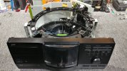
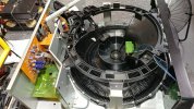
a few more shots of the 200 disc chassis.

jvc xl-mc222 - 4.jpg
not much in the way of circuit boards but there are a few complex chips here and there.

jvc xl-mc222 - 5.jpg
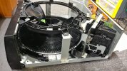
view of the disc loading mech, vertical positioned module on the right.

jvc xl-mc222 - 6.jpg
multiple board sub-assemblies connected via long ribbon cables. lots of sharp edges from the thin metal frame and support structures.
 
Back
Top Bottom